Detection module

a detection module and detection module technology, applied in the field of detection modules, can solve problems such as inconsistent performance within or across product lines

Active Publication Date: 2011-09-15
MESO SCALE TECH LLC
View PDF17 Cites 9 Cited by
  • Summary
  • Abstract
  • Description
  • Claims
  • Application Information

AI Technical Summary

Benefits of technology

[0009]Finally, the invention provides an apparatus for conducting luminescence assays in multi-well plates, the apparatus comprising a light-tight enclosure (LTE), a fluidic assembly, an imaging assembly, a plate assembly capable of supporting and t

Problems solved by technology

Such alterations might lead to inconsistent performance within or acros

Method used


Image

  • Detection module
  • Detection module
  • Detection module

Examples


Embodiment Construction

[0014]The Detailed Description section provides descriptions of certain embodiments of the invention that should not be considered limiting but are intended to illustrate certain inventive aspects. Unless otherwise defined herein, scientific and technical terms used in connection with the present invention shall have the meanings that are commonly understood by those of ordinary skill in the art. Further, unless otherwise required by context, singular terms shall include pluralities and plural terms shall include the singular. The articles “a” and “an” are used herein to refer to one or to more than one (i.e., to at least one) of the grammatical object of the article. By way of example, “an element” means one element or more than one element.

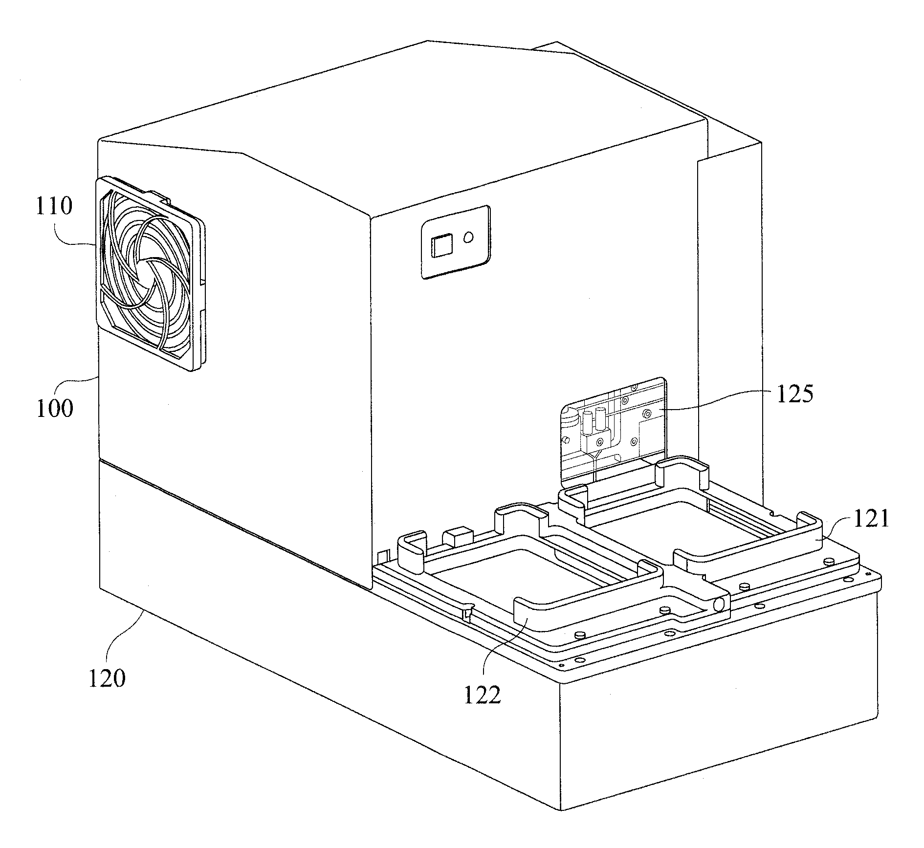
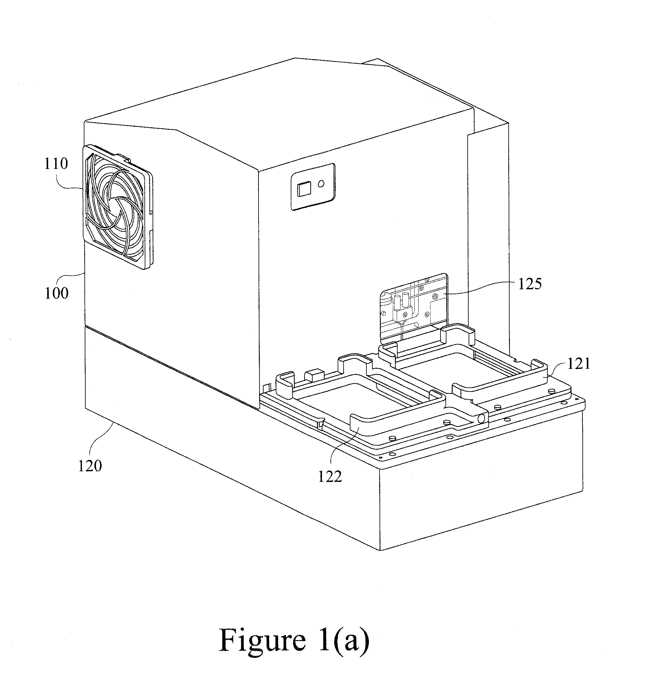
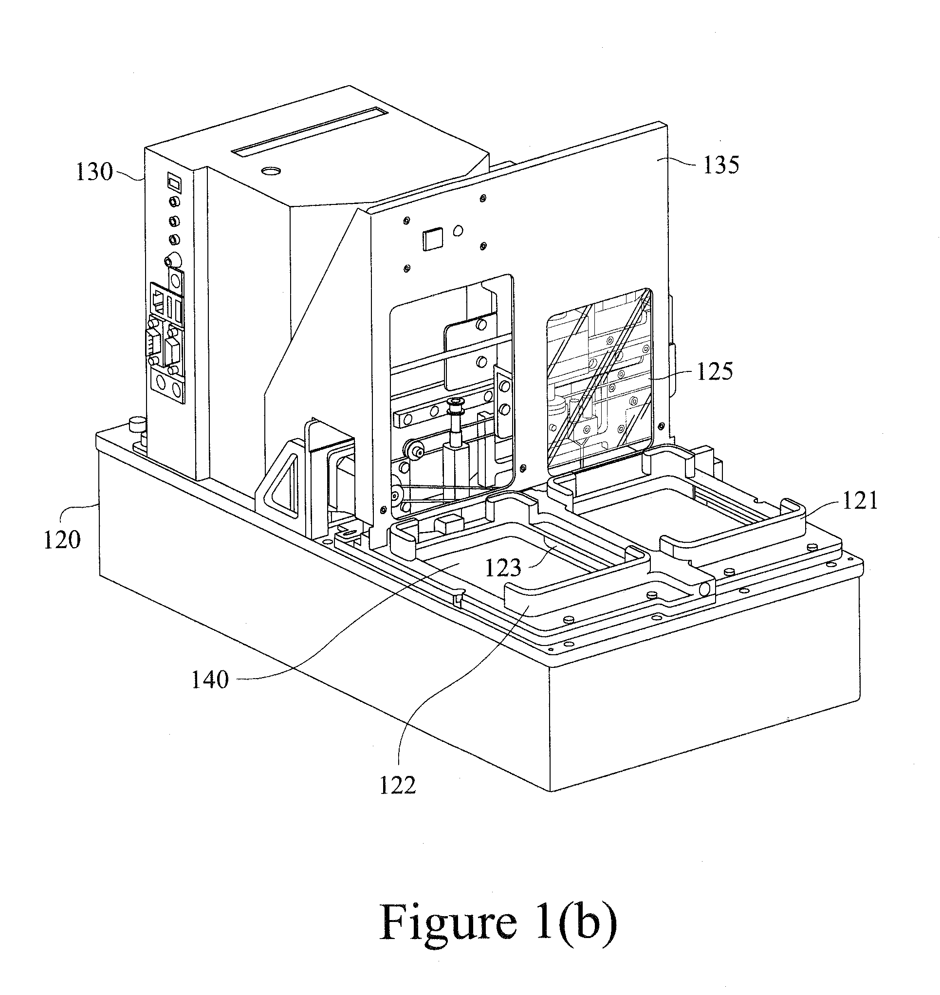
[0015]Described herein is a detection module used with an apparatus for conducting luminescence assays. As used herein, an assay system refers to the apparatus including an integrated detection module, i.e., a detection module that is mounted to...


PUM


Abstract

We describe a detection module useful with an apparatus and/or system for conducting luminescence assays.

Description

CROSS REFERENCE TO RELATED APPLICATIONS[0001]Reference is made to U.S. Provisional Application Nos. 61 / 339,790 and 61 / 339,789, each filed on Mar. 9, 2010; U.S. Provisional Application No. 61 / 123,975, filed Apr. 11, 2008; U.S. Provisional Application No. 60 / 752,475, filed Dec. 21, 2005; U.S. Provisional Application No. 60 / 726,023, filed Oct. 11, 2005; U.S. Provisional Application No. 60 / 752,513, filed Dec. 21, 2005; U.S. application Ser. No. 11 / 642,970, filed Dec. 21, 2006; U.S. application Ser. No. 11 / 642,968, filed Dec. 21, 2006; and U.S. application Ser. No. 12 / 422,081, filed Apr. 10, 2009. The disclosures of each of these applications are incorporated herein by reference in their entireties.FIELD OF THE INVENTION[0002]The invention relates to a detection module used in an apparatus and / or system for conducting assays. Certain embodiments of the apparatus and / or system may be used for conducting automated sampling, sample preparation, and / or sample analysis in a multi-well plate a...

Claims


Application Information

Patent Timeline
IPC IPC(8): H01L27/146H01L31/08H01L27/148
CPCG01N21/6452B01L2200/18B01L2300/021B01L2300/0663B01L2300/0867B01L3/502B01L2200/025B01L2300/0609B01L2300/0654B01L2300/0829G01N21/76G01N33/54366G01N2201/068G01N2201/12
Inventor CLINTON, CHARLES M.WOHLSTADTER, JACOB N.
Owner MESO SCALE TECH LLC
Why Eureka
Try Eureka