
Vehicle wheel assemblies and valves for use with a central tire inflation system

Active Publication Date: 2011-09-15
ROYAL BANK OF CANADA
View PDF66 Cites 23 Cited by
  • Summary
  • Abstract
  • Description
  • Claims
  • Application Information

AI Technical Summary

Benefits of technology

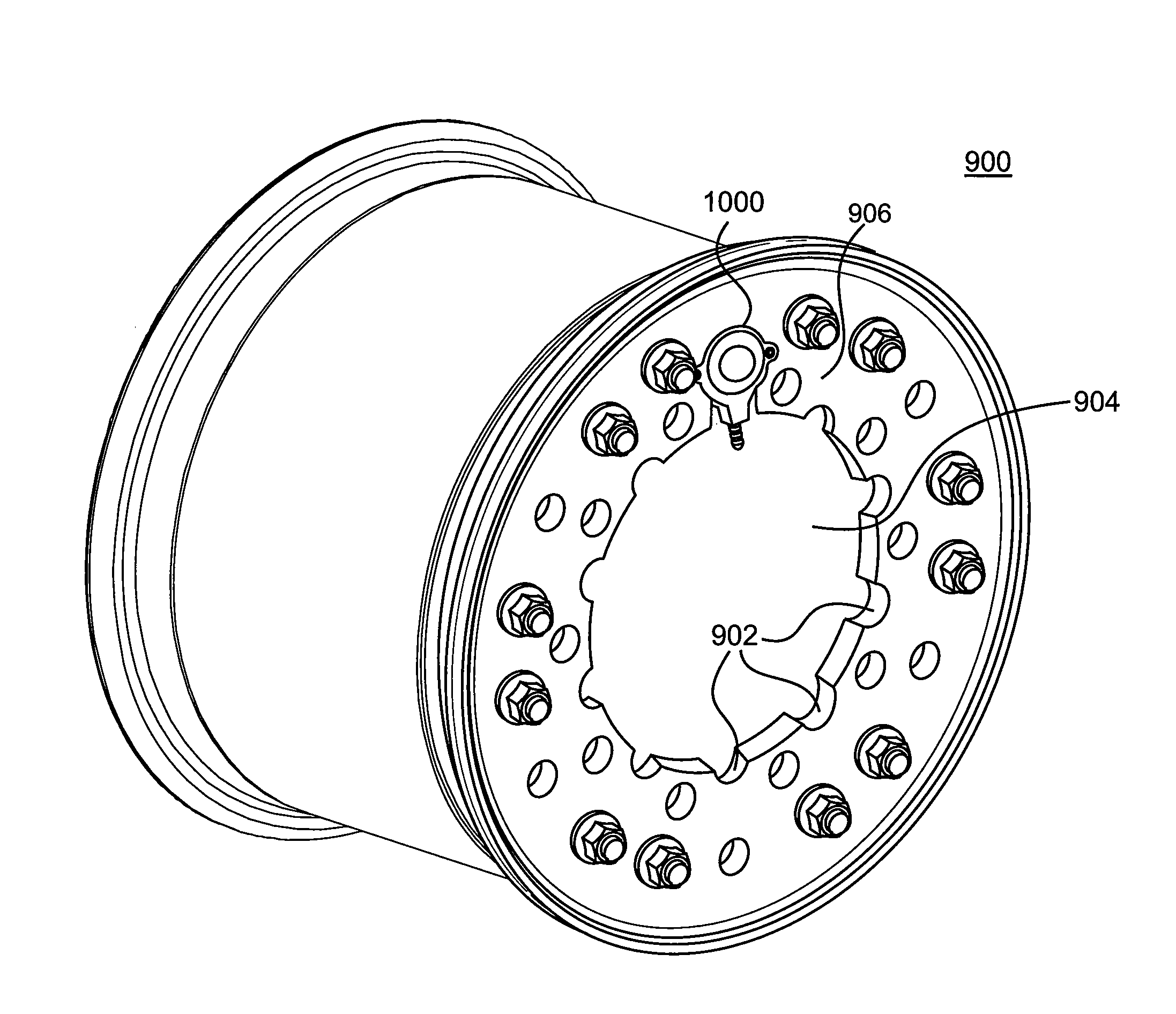
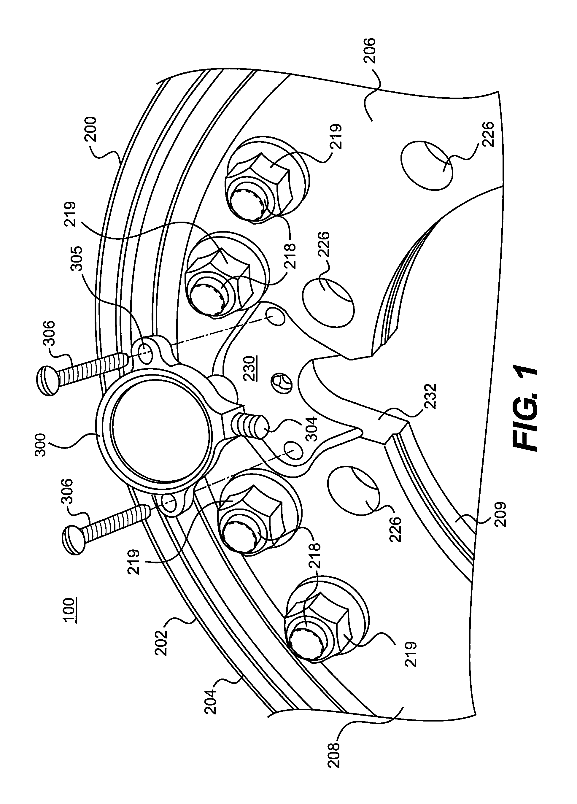
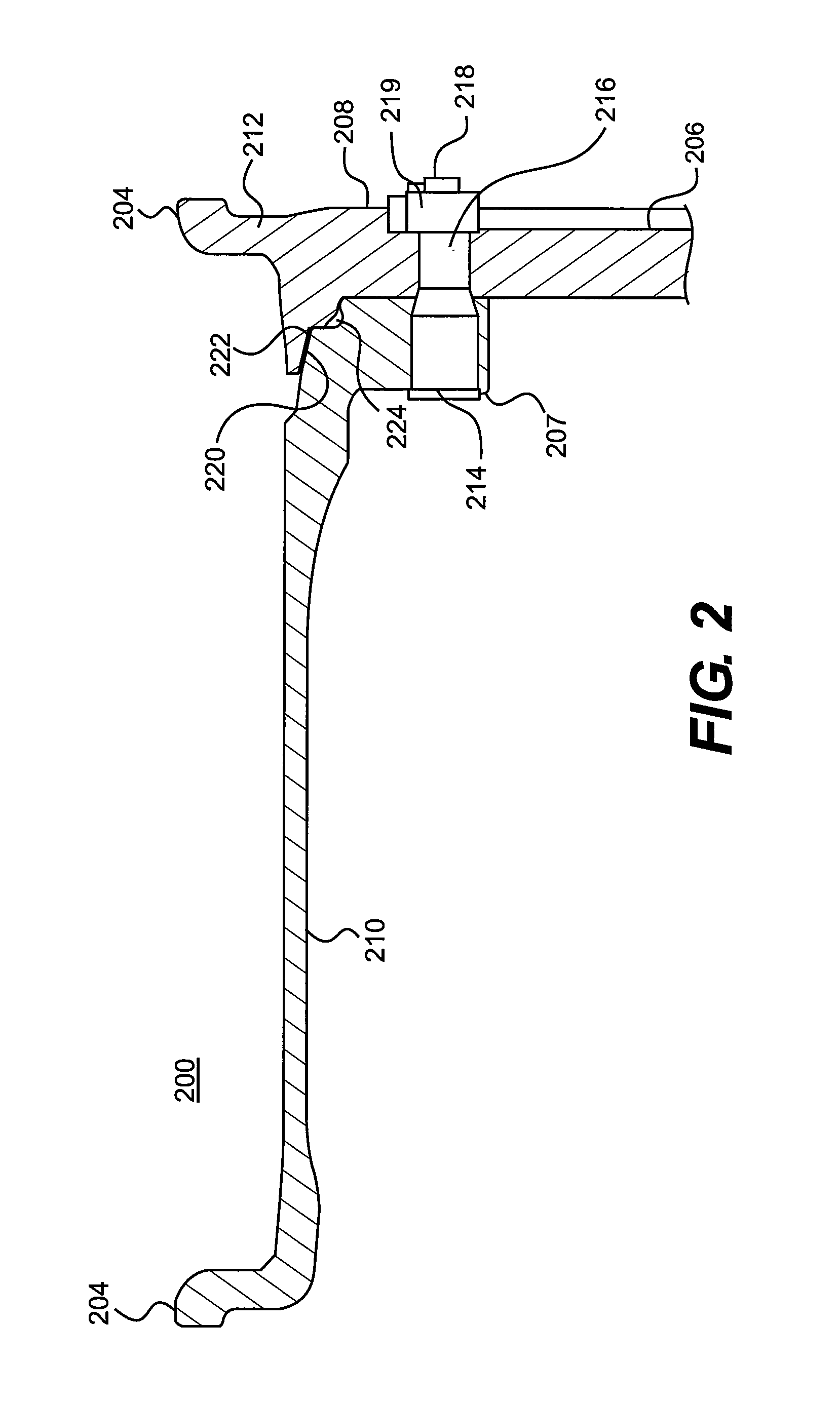
[0009]A vehicle wheel assembly may include a wheel comprising a generally circular rim and a wall extending radially inwardly from the rim. The wall may comprise an inboard side and an outboard side, and have therethrough a central opening. The wheel may also include a wheel duct formed within the wheel. The wheel duct may include a first end and a second end. The wheel assembly may also include a valve secured to the outboard side of the wall. The valve may include a

Problems solved by technology

However, in certain situations, it may be inconvenient or even dangerous (e.g., when the vehicle is deployed in combat situations) for the operator to exit the vehicle to manually adjust the tire pressure.
For example, external conduits may catch on something or be damaged in a variety of other ways.
Given that CTI systems are often employed on vehicles used in rugged or dangerous environments, the risk to external conduits may be considerable.
However, providing an internal duct through the wheel for communicating fluid between a CTI system and a valve also introduces potential difficulties.
For example, the interface between the wheel's fluid duct and other components of the CTI system is susceptible to damage at various stages of the wheel's life (e.g., during manufacture, assembly, maintenance, or in use).
If a wheel's CTI duct becomes damaged, that wheel must likely be discarded.
These seals are also susceptible to damage or decay, which can result in fluid leaking at the interface between the wheel duct and the other components of the CTI system.

Method used


Image

  • Vehicle wheel assemblies and valves for use with a central tire inflation system
  • Vehicle wheel assemblies and valves for use with a central tire inflation system
  • Vehicle wheel assemblies and valves for use with a central tire inflation system

Examples


Embodiment Construction

[0023]The following detailed description refers to the accompanying drawings. Where the same reference numbers are used in the drawings and the following description, such reference numbers refer to the same or similar components or processes. While several exemplary versions and aspects of the invention are described herein, modifications, adaptations and other implementations are possible without departing from the spirit and scope of the invention. For example, substitutions, additions and / or modifications may be made to the components illustrated in the drawings. Accordingly, the following detailed description does not limit the invention. Instead, the proper scope of the invention is defined by the appended claims.

[0024]The present description relates to wheel assemblies, including valves, for use with central tire inflation systems that allow a vehicle's operator to adjust the pressure in the vehicle's tires during operation of the vehicle. More specifically, the present descr...


PUM


Abstract

Wheel assemblies and valves for use with central tire inflation systems are provided. A wheel assembly may include a wheel having a rim and a wall extending radially inwardly from the rim. The wall may include an inboard side and an outboard side, and a central opening therethrough. The wheel may include a wheel duct for communicating pressurized fluid to a tire. A valve may be secured to the wheel wall. The valve may include an inboard side and an outboard side. The valve may include a hub interface adapted to extend from its inboard side. The hub interface may be adapted to extend around the wheel wall. The valve may include an inlet duct opening on the hub interface to communicate with a duct in a wheel hub on which the wheel is mounted. The valve may also include an outlet duct configured to communicate with the wheel duct.

Description

BACKGROUND[0001]I. Field[0002]The present disclosure relates to vehicle wheel assemblies and valves for use with a central tire inflation system.[0003]II. Background Information[0004]Certain vehicles, such as those designed for some military applications, are required to travel over a variety of terrains. Because optimal tire pressure varies depending on the terrain, it may be desirable to adjust tire pressure during use. For example, when transitioning from an asphalt highway to a softer surface (e.g., sand, dirt, or snow), it is advisable to lower the vehicle's tire pressure in order to increase the tire's surface contact area, distributing the vehicle's weight over a larger area. However, in certain situations, it may be inconvenient or even dangerous (e.g., when the vehicle is deployed in combat situations) for the operator to exit the vehicle to manually adjust the tire pressure.[0005]Central tire inflation (CTI) systems allow a vehicle's operator to adjust tire pressure withou...

Claims


Application Information

Patent Timeline
IPC IPC(8): B60C29/02B60B3/00F16K15/20
CPCB60C23/003B60C2200/14B60C29/02Y10T137/3584B60C23/00363B60C23/00318B60C23/00354
Inventor EATON, JAMES K.KRITZELL, DAVID E.SHY, DANIEL E.HOHMAN, DONALD A.
Owner ROYAL BANK OF CANADA
Learn More