Imaging apparatus for imaging a heart

Inactive Publication Date: 2011-09-22
KONINKLIJKE PHILIPS ELECTRONICS NV
View PDF7 Cites 46 Cited by
  • Summary
  • Abstract
  • Description
  • Claims
  • Application Information

AI Technical Summary

Benefits of technology

[0004]It is an object of the present invention to provide an imaging apparatus, an imaging method and an imaging computer program for imaging a heart, wherein

Problems solved by technology

The system has the drawback that a tremendous volume of electroanatomical data is presented that, for example, an electrophysiologist must mentally parse and interpret in order to determine,

Method used


Image

  • Imaging apparatus for imaging a heart
  • Imaging apparatus for imaging a heart
  • Imaging apparatus for imaging a heart

Examples


Embodiment Construction

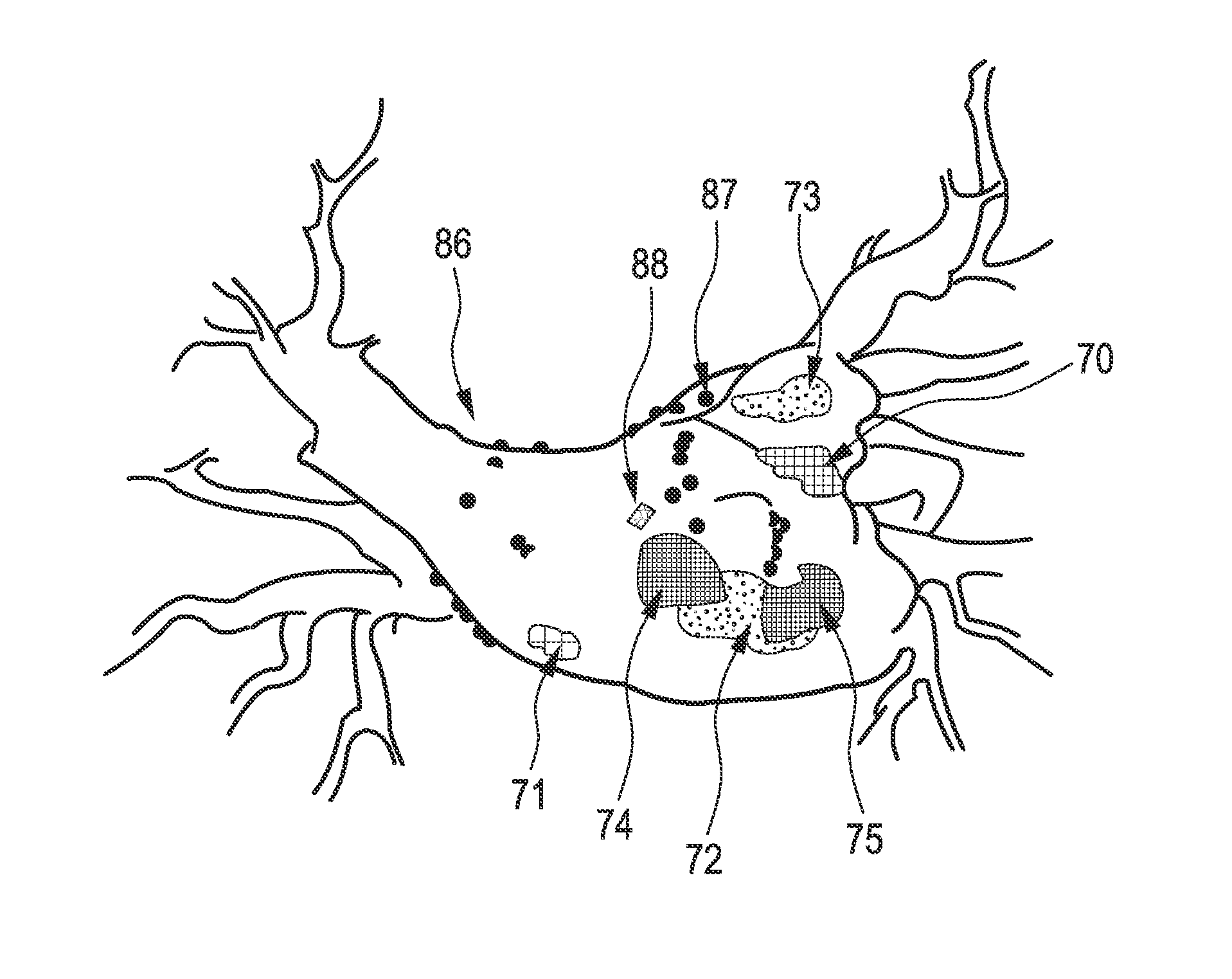
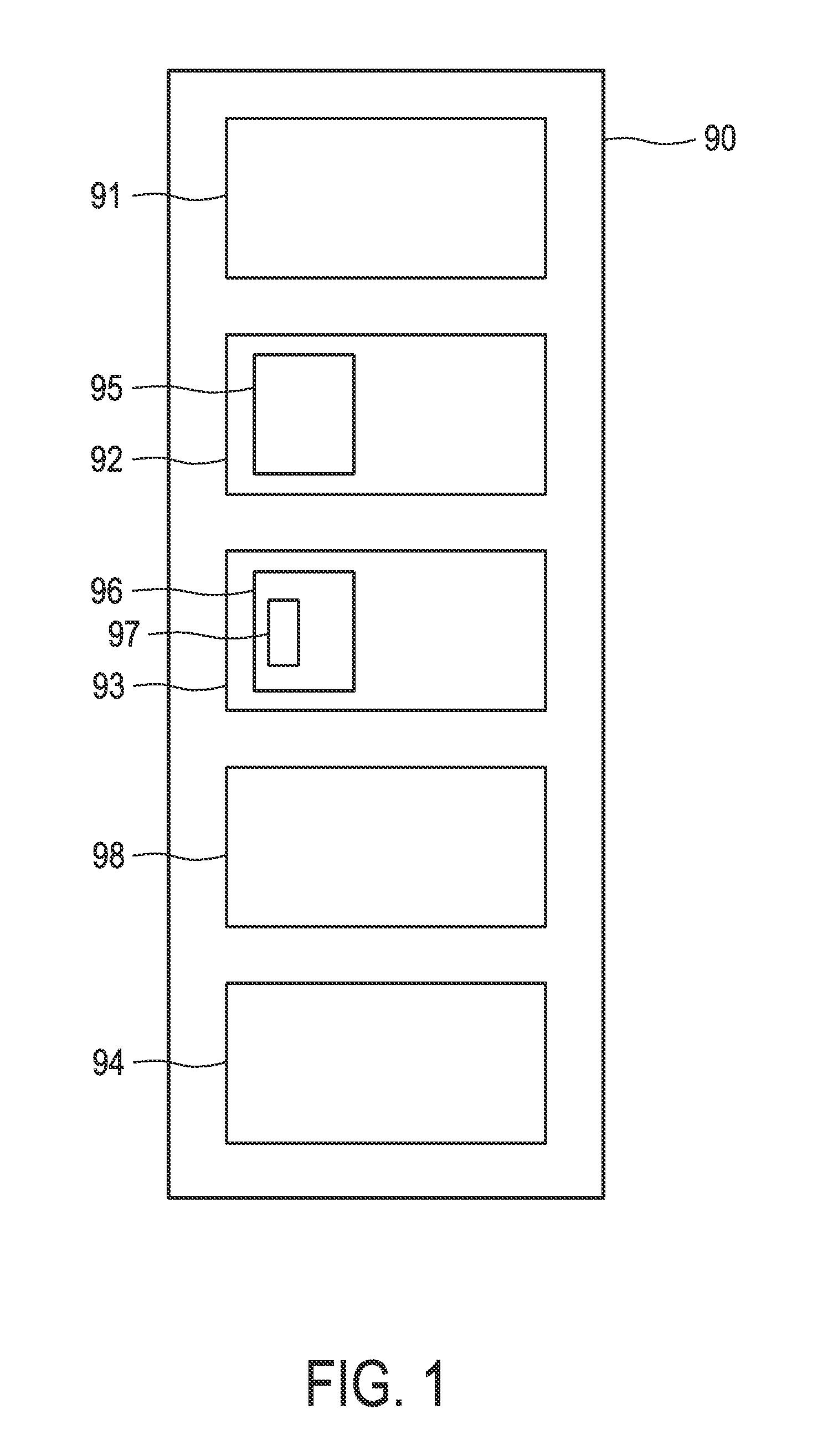
[0062]FIG. 1 shows schematically and exemplarily an embodiment 90 of an imaging apparatus for imaging a heart. The imaging apparatus comprises a property type providing unit 91 for providing property types of the heart at different locations of the heart, a first site determination unit 92 for determining a first site of the heart, wherein the first site comprises a first property type of the provided property types, and a second site determination unit 93 for determining a second site of the heart, wherein the second site comprises a second property type of the provided property types and wherein the second site has a causal relation to the first site. The imaging apparatus 90 further comprises a display unit 94 for displaying the first site and the second site.

[0063]The first site and the second site are causally related if the property type of at least one of the first site and the second site causes or promotes the property type of the other of the first site and the second site...


PUM


Abstract

An imaging apparatus for imaging a heart is provided, wherein the imaging of the heart is improved such that conclusions about regions of the heart having an abnormal behaviour can be made more accurate and more optimal. The imaging apparatus comprises a first site determination unit for determining a first site of the heart comprising a first property type like a fractionated electrogram (70,71,74,75) and a second site determination unit for determining a second site comprising a second property type like a ganglionated plexus (72,73). The first site and the second site are causally related and displayed on a display unit. Since the displayed first and second sites are causally related to each other, a further information is given, i.e. the causal relation, which assists a user in finding regions of the heart showing an abnormal behaviour.

Description

FIELD OF THE INVENTION[0001]The present invention relates to an imaging apparatus, an imaging method and an imaging computer program for imaging a heart.BACKGROUND OF THE INVENTION[0002]The article “Integration of Three-Dimensional Scar Maps for Ventricular Tachycardia Ablation With Positron Emission Tomography-Computed Tomography”, T. Dickfeld et al., Journal of the American College of Cardiology Foundation, Cardiovascular Imaging, 1:73-82, 2008 describes a system for determining sites of scar tissue of a heart and for co-displaying these sites with an electroanatomical map of the heart.[0003]The system has the drawback that a tremendous volume of electroanatomical data is presented that, for example, an electrophysiologist must mentally parse and interpret in order to determine, for example, optimal ablation sites. This mental process is time-consuming and often difficult and may lead to inaccurate or sub-optimal conclusions, in particular, on optimal ablation sites.SUMMARY OF THE...

Claims


Application Information

Patent Timeline
IPC IPC(8): A61B5/02A61B5/296
CPCA61B5/02007A61B5/0422A61B5/055A61B5/06A61B6/12A61B6/503A61B2018/00839A61B8/0883A61B18/1492A61B18/20A61B2018/00577A61B2018/00702A61B2018/00791A61B8/0833A61B5/287
Inventor BARLEY, MAYA ELLAKAHLERT, JOACHIM
Owner KONINKLIJKE PHILIPS ELECTRONICS NV
Why Eureka
Try Eureka