
Tooth shade analyzer system and methods

Inactive Publication Date: 2005-06-02
LEHMANN MARYANN
View PDF74 Cites 3 Cited by
  • Summary
  • Abstract
  • Description
  • Claims
  • Application Information

AI Technical Summary

Benefits of technology

[0014] For optimum results, either the patient's tooth or a tooth shade is imaged at a controlled, reproducible distance, and a reference color to assist in determining the patient's tooth color from the color information of the image. Also, the patient's teeth are cosmetically whitened before conducting the electronic imaging step.
[0017] In order to optimize the color determining step, one of the patient's tooth or a tooth shade or both can be imaged at a controlled, reproducible distance. The step of isolating the patient's tooth from stray light can be used to enhance the image. Also, a reference color can be provided to assist in determining the patient's tooth color from the color information of the image. When used, it is helpful to surround the patient's tooth with the reference color before the imaging step. Often, the patient's tooth is cosmetically whitened before conducting the electronic imaging step.
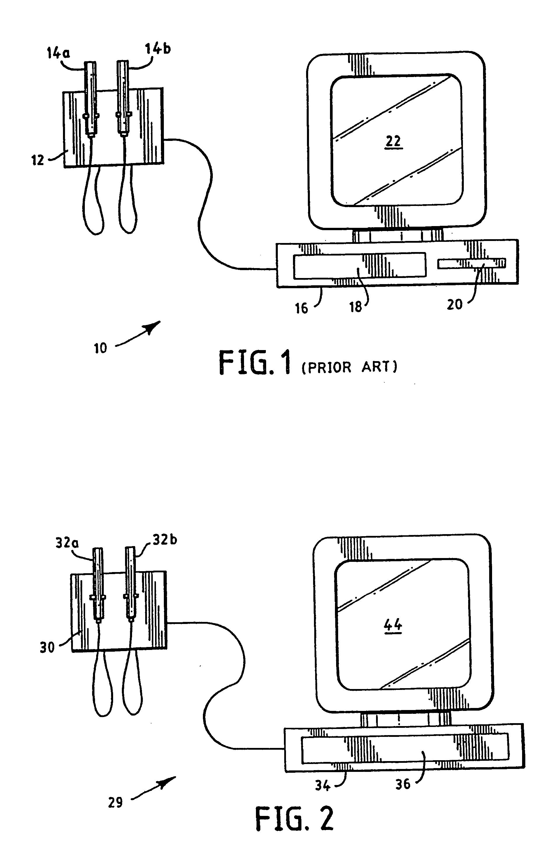
[0021] The color processor preferably includes electronic circuitry which determines RGB chromaticities of the color image, each of the plurality of tooth shades has a corresponding RBG representation of the tooth color, and the electronic circuitry quantitatively compares the RGB chromaticities with the RGB representation of each of the tooth shades, thus comparing or identifying a tooth shade based upon a comparison of the chromaticities and the RGB representations. For optimum results, the system further comprises a sample box (or isolation sleeve) for isolating the tooth from stray light. This isolation sleeve preferably includes a first compartment that contains a reference color and a second compartment for receiving the patient's tooth or a reference shade. It also may have a side wall of a length which assists in obtaining reproducible results by positioning the camera at a controlled distance from the patient's tooth or the tooth shade. Even without the isolation sleeve, the system may include a reference card having a background color to enhance the image of the patient's tooth, the card optionally including an opening for receiving the patient's tooth or a reference shade.

Problems solved by technology

These intraoral camera systems are rapidly becoming key complex diagnostic and treatment planning.
Often, there is a break-down or failure in this communication, resulting in a poor shade match for the patient.
This too can result in improper shade matching.
To further complicate the color-matching process, some dentists are simply not skilled in taking and determining shade information.

Method used


Image

  • Tooth shade analyzer system and methods
  • Tooth shade analyzer system and methods
  • Tooth shade analyzer system and methods

Examples


example

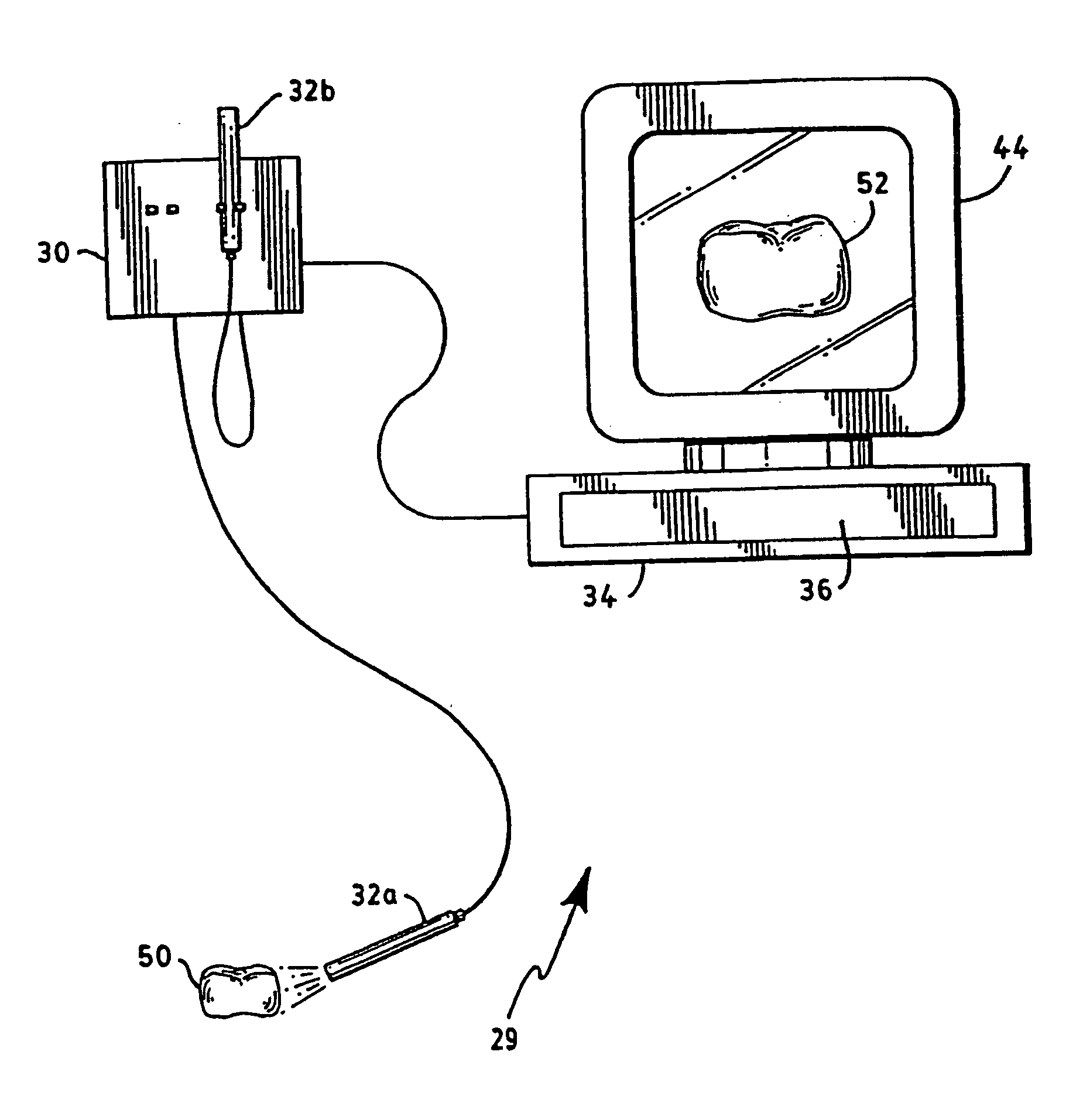
[0072] The following example illustrates the use of a CCD camera to provide a dental color match for a patient's tooth. The camera was connected to a Personal Computer (“PC”). Several images of the patient's tooth were taken and compared for consistency and definition of color variance. To verify consistency, a software program was used to interface with the camera to take snapshot images of Vita Limun Vacuum Shades using the camera. The images were be stored on the PC for later analysis. All images included the sample media and color reference at the same location in the frame. A software program was written to analyze the stored snapshots. Evaluation areas (sample and reference) were sampled and results of the color analysis were presented. The color reference was used to overcome the auto-brightness which could not be disabled on the camera. The software automatically adjusted the sample results using the color reference.

[0073] The following camera was used and found to be prefe...


PUM


Abstract

The invention relates to a computer readable medium comprising one or more programs for carrying out a method for determining a patient's tooth shade. The method generally includes the steps of generating an image of a patient's tooth wherein the image includes color information representative of the patient's tooth shade; storing color information representative of a plurality of tooth shades; and comparing the color information of the image with the stored tooth shade color information to identify one or more tooth shades having a combined color that corresponds to the patient's tooth shade, and the color information that is obtained may be displayed to identify one or more tooth shades having a combined color corresponding to the determined tooth color. Preferably, the displayed data includes RGB chromaticities of the color image, and the patient's tooth color is determined by averaging the color information at selected locations of the image which correspond to different spatial locations of the patient's tooth. If desired, the color information of the patient's tooth can be electronically stored for use at a later time.

Description

CROSS-REFERENCE TO RELATED APPLICATIONS: [0001] This application is a continuation of U.S. application Ser. No. 10 / 407,165 filed Apr. 7, 2003, which is a continuation of U.S. application Ser. No. 10 / 057,663 filed Jan. 25, 2002, now U.S. Pat. No. 6,561,800, which is a continuation of U.S. application Ser. No. 09 / 918,147 filed Jul. 30, 2001, now U.S. Pat. No. 6,358,047, which application is a continuation of U.S. application Ser. No. 09 / 688,542 filed Oct. 16, 2000, now U.S. Pat. No. 6,305,933, which application is a continuation of U.S. application Ser. No. 09 / 385,615 filed Aug. 30, 1999, now U.S. Pat. No. 6,132,210, which is a continuation of U.S. application Ser. No. 09 / 082,030, filed May 20, 1998, now U.S. Pat. No. 5,961,324, which is a continuation-in-part of U.S. application Ser. No. 08 / 494,979, filed Jun. 26, 1995, now U.S. Pat. No. 5,766,006.BACKGROUND ART [0002] In dentistry, there has been a shift in recent years from a philosophy of drilling and filling to one of prevention ...

Claims


Application Information

Patent Timeline
IPC IPC(8): A61C19/10G01J3/46G01J3/50G01J3/52G01N21/25
CPCA61C19/10G01J3/46G01J3/462G01J3/463G01N21/25G01J3/508G01J3/513G01J3/52G01J3/50
Inventor LEHMANN, MARYANN
Owner LEHMANN MARYANN
Learn More