
Dual Activated Actuator Cap

a technology of actuator cap and actuator, which is applied in the direction of closure using stoppers, liquid handling, instruments, etc., can solve the problems of difficult mold or manufacture of triggers, relative awkward gripping and finger placement, and high switching costs

Active Publication Date: 2011-09-29
SC JOHNSON & SON INC
View PDF51 Cites 40 Cited by
  • Summary
  • Abstract
  • Description
  • Claims
  • Application Information

AI Technical Summary

Problems solved by technology

Buttons are a tried and true approach, but the relatively awkward gripping and finger placement may be uncomfortable for some.
While trigger mechanisms have evolved as a viable alternative, such triggers may be difficult to mold or manufacture because of the numerous parts necessary for adequate functionality.
Additionally, there may be switching costs that limit the viability of actuating triggers as an alternative for users who have grown accustomed to actuating buttons.

Method used


Image

  • Dual Activated Actuator Cap
  • Dual Activated Actuator Cap
  • Dual Activated Actuator Cap

Examples


Embodiment Construction

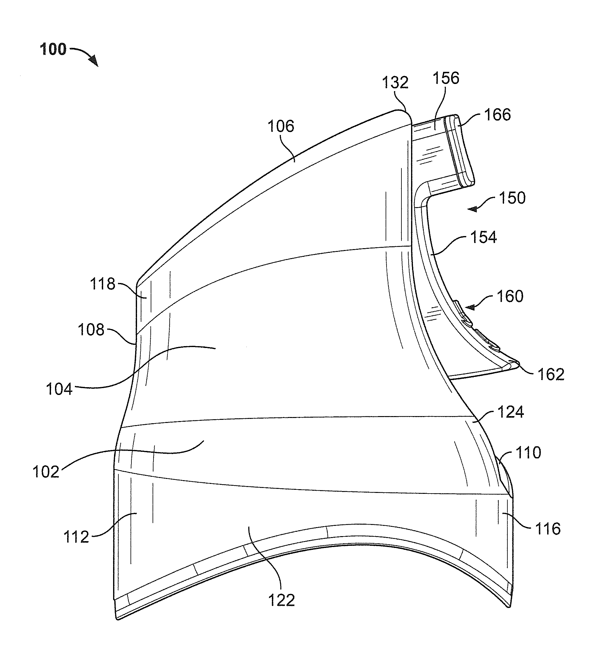
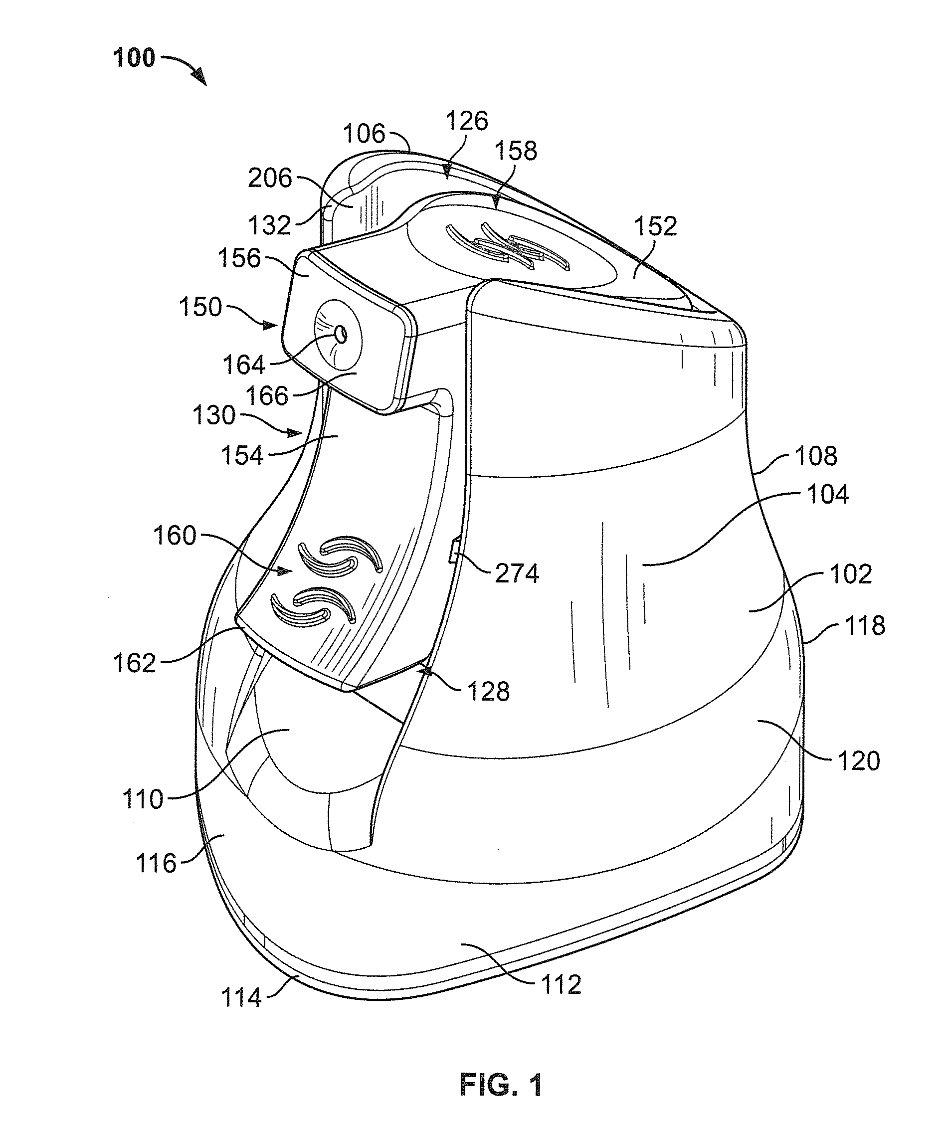
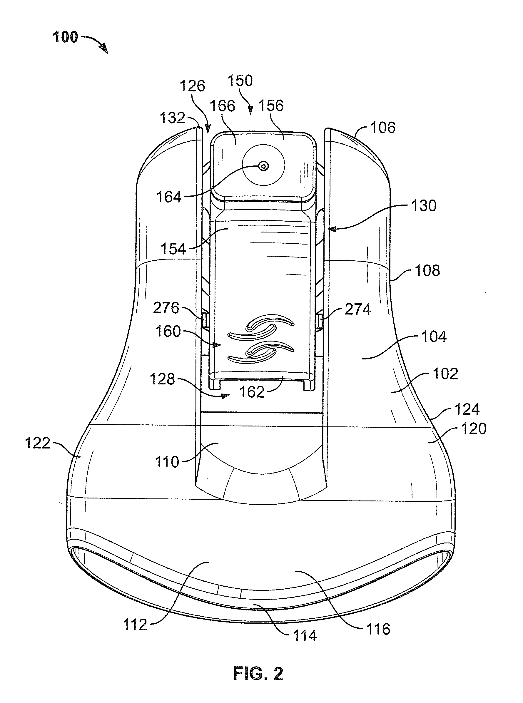
[0026]As illustrated in FIGS. 1-6, a dual activated actuator cap 100 is presented, which includes a housing 102. The housing 102 includes a sidewall 104 having a top portion 106, a neck portion 108, a lip portion 110, and a lower skirt portion 112. The sidewall 104 has a generally bell-shaped appearance.

[0027]With reference to FIGS. 2-5, the lower skirt portion 112 of the sidewall 104 is cylindrical. A bottom edge 114 of the lower skirt portion 112 is imparted with a curve so that the bottom edge 114 of the portion 112 appears concave when viewed from front and rear sides 116, 118 and convex when viewed from left and right sides 120, 122, respectively. The sidewall 104 tapers upwardly and inwardly from the lower skirt portion 112 in a convex manner toward an inflection point 124, whereupon the sidewall 104 is imparted with a concave appearance. When viewed from the front and rear sides 116, 118, the sidewall 104 adjacent the neck portion 108 appears to taper upwardly in a uniformly ...


PUM


Abstract

A single piece actuator includes first and second actuating members. A dispensing orifice is disposed between the first and second actuating members. A manifold is in fluid communication with the dispensing orifice. The manifold includes a base adapted to impinge a valve stem of a container and place same in fluid communication with the manifold.

Description

CROSS REFERENCE TO RELATED APPLICATIONS[0001]Not ApplicableREFERENCE REGARDING FEDERALLY SPONSORED RESEARCH OR DEVELOPMENT[0002]Not ApplicableSEQUENTIAL LISTING[0003]Not ApplicableBACKGROUND OF THE INVENTION[0004]1. Field of the Invention[0005]The present invention generally relates to a device for dispensing product from a container. More particularly, the present invention relates to a dual activated actuator cap for engaging and actuating a valve assembly of a pressurized container.[0006]2. Description of Related Art[0007]Pressurized containers are commonly used to store and dispense volatile materials, such as air fresheners, deodorants, insecticides, germicides, decongestants, perfumes, and the like. The volatile materials are typically stored in a pressurized and liquefied state within the container. A release valve with an outwardly extending valve stem may be provided to facilitate the release of the volatile material, whereby activation of the valve via the valve stem cause...

Claims


Application Information

Patent Timeline
Patent Type & Authority Applications(United States)
IPC IPC(8): B65D83/00B23P11/00
CPCB65D83/205Y10T29/49826B65D83/206
Inventor ADAMS, MARY BETHCHRISTIANSON, JEFFREY J.ANDERSEN, DANIEL A.XIN, HANGROSSMAN, MATTHEWMORRIS, KIT R.
Owner SC JOHNSON & SON INC
Features
  • Generate Ideas
  • Intellectual Property
  • Life Sciences
  • Materials
  • Tech Scout
  • Unparalleled Data Quality
  • Higher Quality Content
  • 60% Fewer Hallucinations
Learn More