Lighting device with throw forward reflector

a technology of reflector and light source, which is applied in outdoor lighting, lighting and heating equipment, lighting source combinations, etc., can solve the problems of not being practical or cost effective to install additional lighting fixtures over such lateral areas, and the amount of light projected laterally is often insufficient to illuminate such lateral areas

Inactive Publication Date: 2011-09-29
ORION ENERGY SYST INC
View PDF49 Cites 62 Cited by
  • Summary
  • Abstract
  • Description
  • Claims
  • Application Information

AI Technical Summary

Problems solved by technology

Although the light projected downwardly by such known reflectors also tends to migrate laterally to some degree, the amount of light projected laterally is often insufficient to illuminate such lateral areas.
However, in some cases it may not be practical or cost effective to install additional lighting fixture(s) over such lateral areas.
Also, it may not be practical to angle such lighting fixtures upward, because for interior applications the lighting devices may need to fit within the plane of a ceiling, and for external applications, angling such lighting fixtures upward may result in increased wind loading on the fixture and / or may not provide “full cutoff” or be “dark-sky” compliant (i.e. cause little or no light to be cast upwardly above a horizontal plane).

Method used


Image

  • Lighting device with throw forward reflector
  • Lighting device with throw forward reflector
  • Lighting device with throw forward reflector

Examples


Embodiment Construction

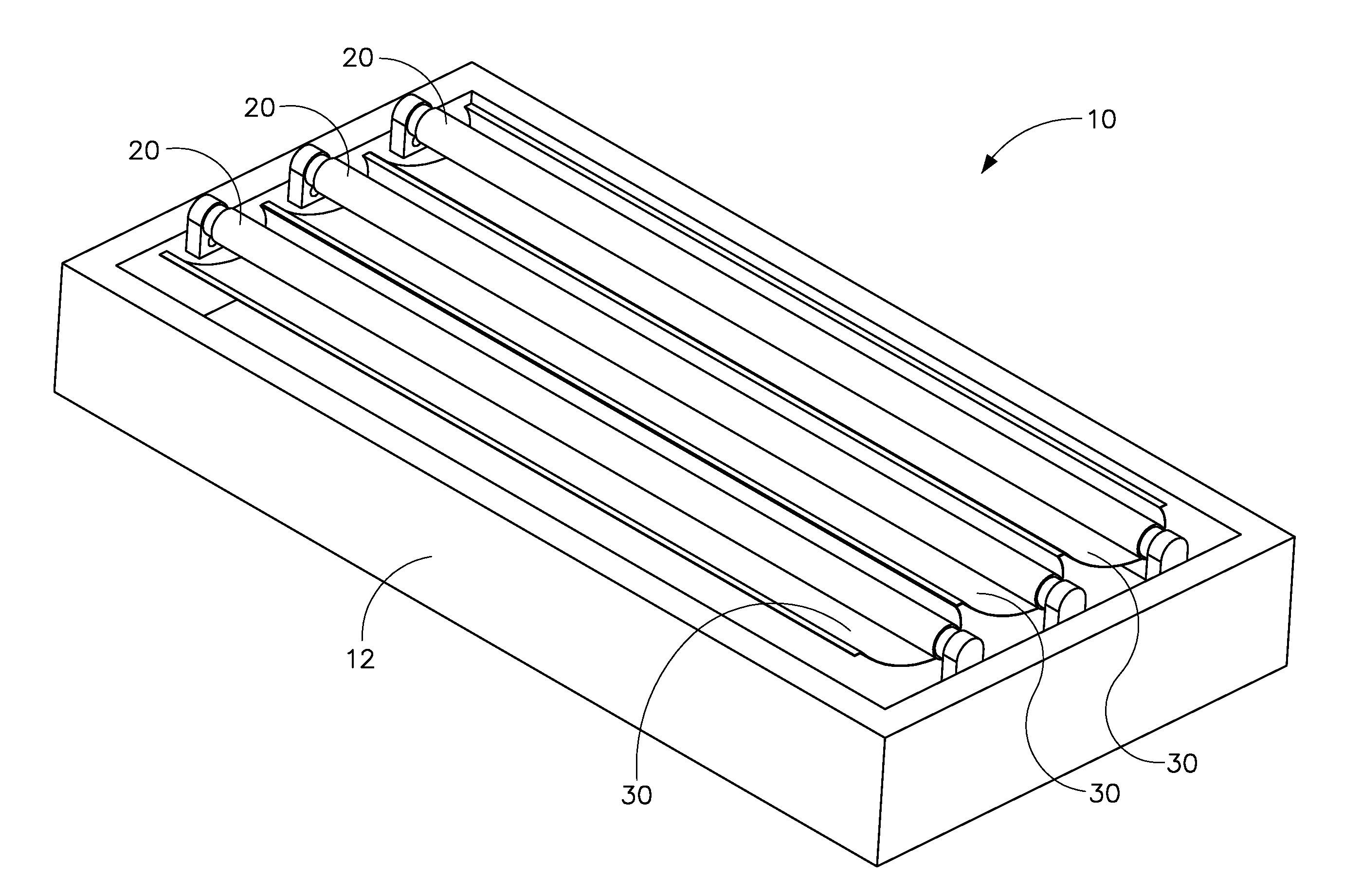
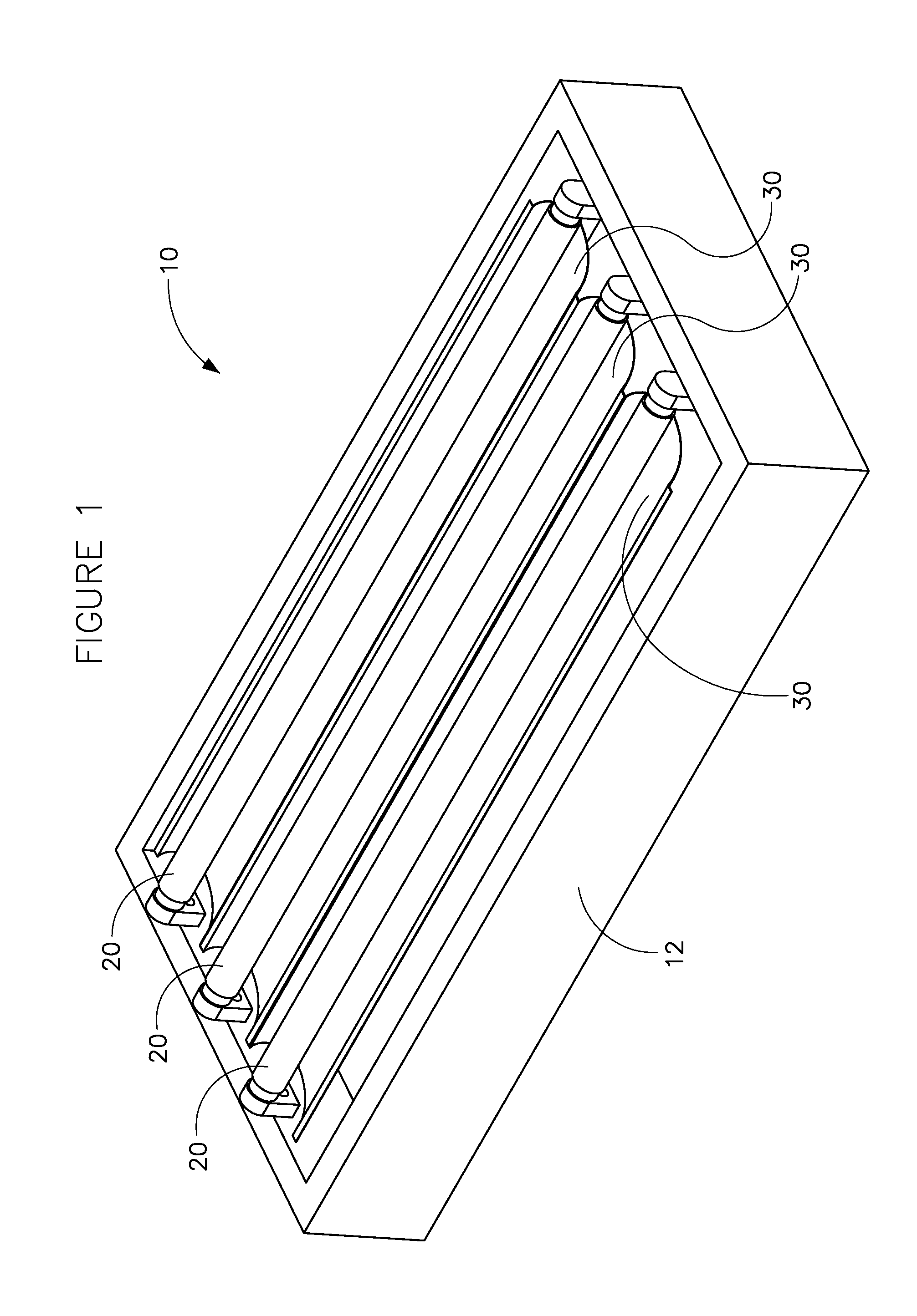
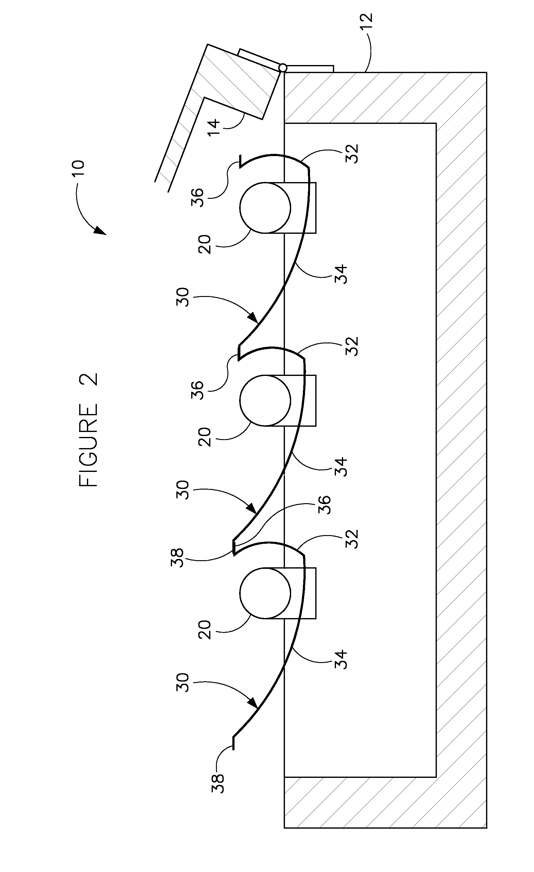
Referring to FIGS. 1 and 2, a lighting device 10 (e.g. fixture, appliance, etc.) having a generally planar or rectangular shape with a body 12 and a cover 14 is shown according to an exemplary embodiment to include one or more light sources 20 (shown for example as three (3) elongated high intensity fluorescent light bulbs), and an elongated reflector 30 having an asymmetric cross sectional geometry (e.g. profile, shape, formation, etc.) configured to cast light in a forward direction (i.e. at a non-perpendicular angle with respect to the plane of the lighting device). Reflector 30 is shown and described by way of example as a single reflector associated with a single light source, that is, one reflector for each light source where adjacent edges or flanges of the reflectors may overlap and may be secured to one another. However, according to alternative embodiments, a single reflector may be provided having a suitable number of reflective geometries that correspond to the number of...


PUM


Abstract

A lighting device with a throw forward reflector includes a body, at least one light source coupled to the body, and a reflector with an asymmetric cross sectional geometry coupled to the body and at least partially about the light source to project light from the light source at an angle that is non-perpendicular to a plane of the body. A throw forward reflector includes an elongated reflector body formed from a sheet of material and has an asymmetric cross sectional profile, the profile comprising a compound radius having a first curved segment defined by a first radius and a second curved segment defined by a second radius that is greater than the first radius, and a crease extending at least partially along the length of the reflector body and defining an interface between the first curved segment and the second curved segment.

Description

FIELDThe field of the disclosure relates generally to lighting devices. More specifically, the disclosure relates to a fluorescent lighting device with a reflector having a geometry configured to project light downward and outward. More particularly, the disclosure relates to a fluorescent lighting device with one or more elongated and asymmetrically shaped reflectors configured to project light in a downward and forward direction (i.e. “throw forward”).BACKGROUNDThis section is intended to provide a background or context to the invention recited in the claims. The description herein may include concepts that could be pursued, but are not necessarily ones that have been previously conceived or pursued. Therefore, unless otherwise indicated herein, what is described in this section is not prior art to the description and claims in this application and is not admitted to be prior art by inclusion in this section.Lighting devices such as light fixtures for interior applications (e.g. o...

Claims


Application Information

Patent Timeline
Patent Type & Authority Applications(United States)
IPC IPC(8): F21V7/00
CPCF21V7/005F21V7/09F21Y2103/00F21W2131/105F21W2131/107F21W2131/103F21Y2113/00
Inventor VERFUERTH, NEAL R.WETENKAMP, KENNETH J.
Owner ORION ENERGY SYST INC
Why Eureka
Try Eureka