
Method and system for orthodontic diagnosis

a technology for orthodontics and treatment, applied in the field of orthodontics, can solve the problems of tooth movement, bone remodeling, and time-consuming process, and achieve the effect of reducing the number of patients, and reducing the number of procedures

Active Publication Date: 2011-10-06
BATESOLE MARK
View PDF8 Cites 57 Cited by
  • Summary
  • Abstract
  • Description
  • Claims
  • Application Information

AI Technical Summary

Benefits of technology

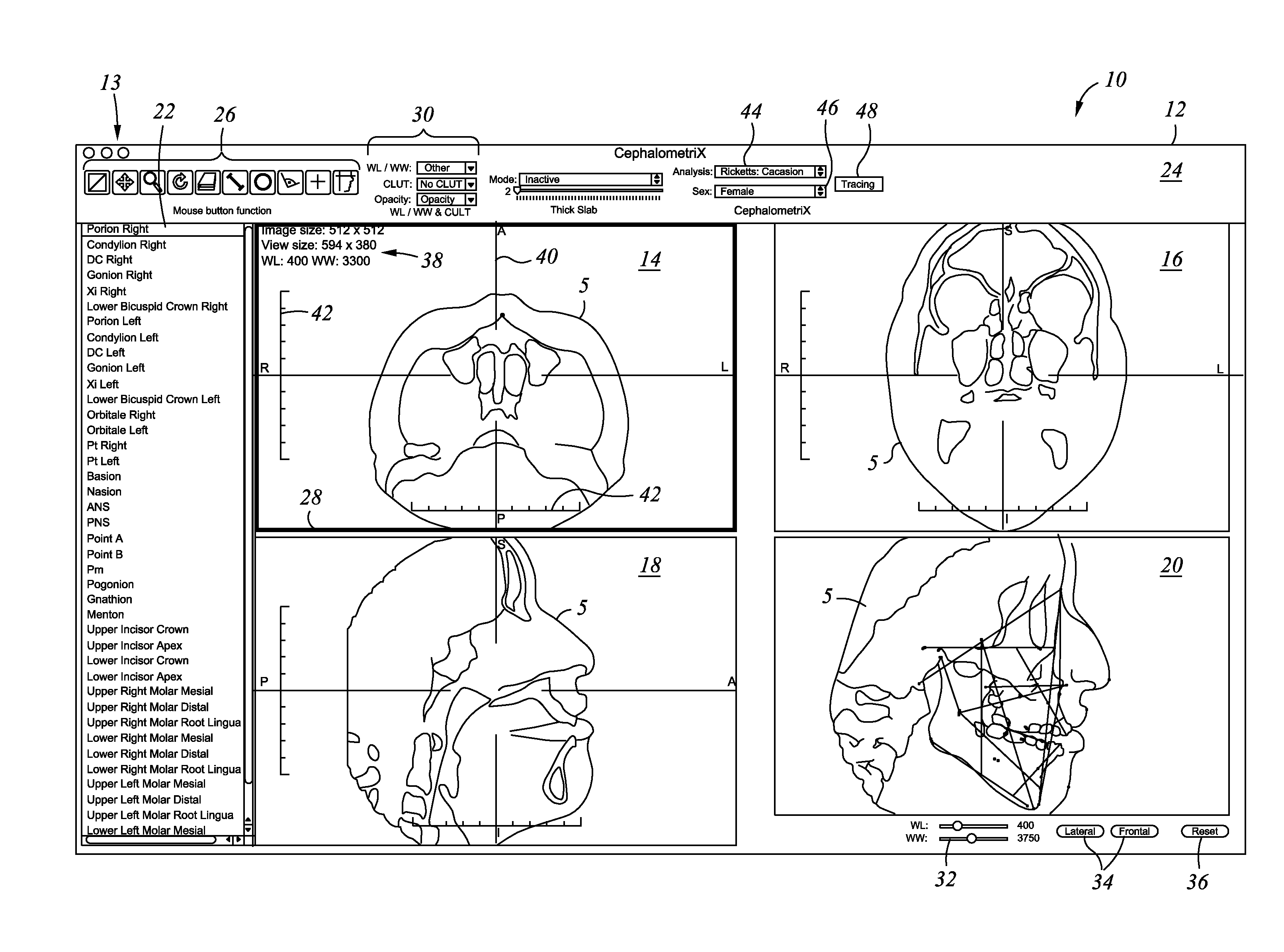
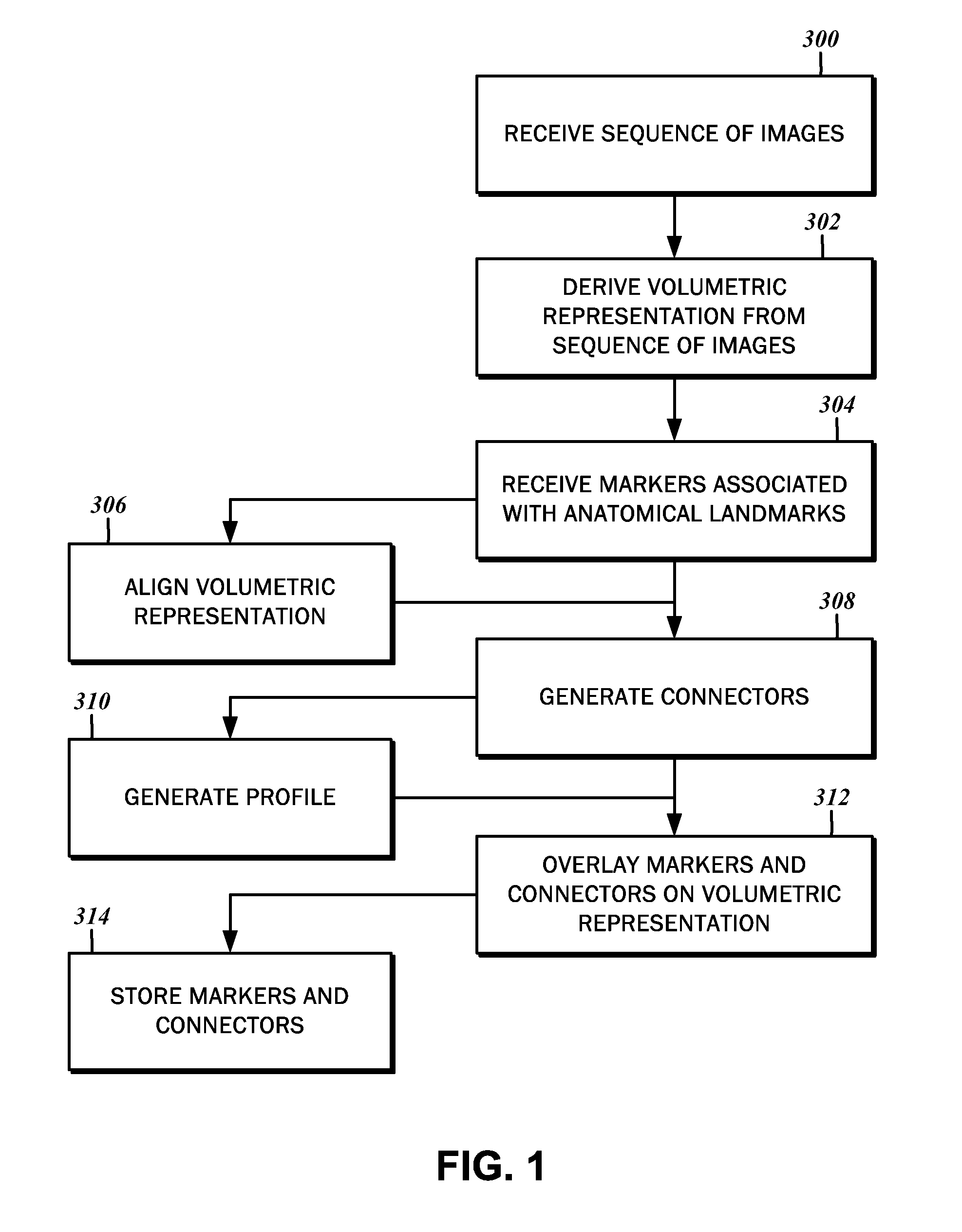
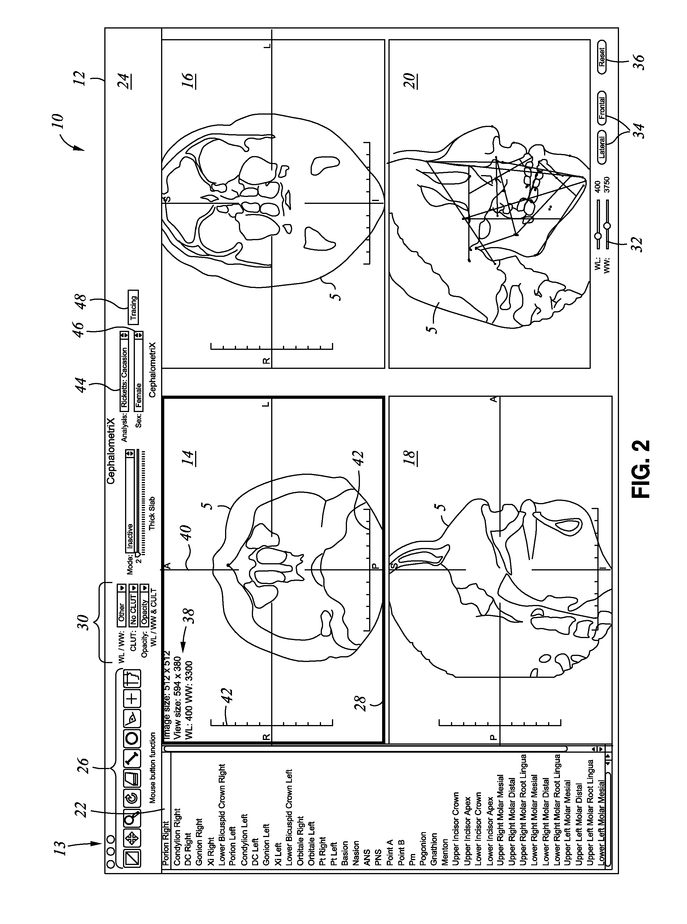
[0012]In accordance with one embodiment of the present disclosure, a method for generating a cephalometric analysis of an orthodontic patient is contemplated. The method includes receiving a sequence of images that may each correspond to a specific anatomical plane of the orthodontic patient. Thereafter, a volumetric representation of the orthodontic patient may be derived from a combination of the sequence of the images. One or more markers are then received. The markers may be associated with particular anatomical landmarks of

Problems solved by technology

The wire exerts a force on the bracket, which in turn exerts a force on the teeth, thereby causing the teeth to move.
More particularly, stresses created within the periodontal ligament by the archwire results in bone remodeling, where bone is created on one side and resorbed on the other side.
That proved to be a tedious and time-consuming process.
Accuracy and repeatability was also problematic.
However, the process remained tethered to the two dimensional sphere, and was inadequate for an inherently three-dimensional environment.
With respect to cephalometric analysis, updated radiograms are essential, and the initial cephalogram alone is insufficient.
One difficulty associated with earlier radiograms is the deviations of the positioning of the head from one image to another.
Thus, tracking the patient's progress based on comparisons of the different cephalograms proved to be difficult.
These modalities are capable of generating three-dimensional images, but typically lack cephalostats.

Method used


Image

  • Method and system for orthodontic diagnosis
  • Method and system for orthodontic diagnosis
  • Method and system for orthodontic diagnosis

Examples


Embodiment Construction

[0026]The detailed description set forth below in connection with the appended drawings is intended as a description of certain embodiments of the present disclosure, and is not intended to represent the only forms that may be developed or utilized. The description sets forth the various functions in connection with the illustrated embodiments, but it is to be understood, however, that the same or equivalent functions may be accomplished by different embodiments that are also intended to be encompassed within the scope of the present disclosure. It is further understood that the use of relational terms such as top and bottom, first and second, and the like are used solely to distinguish one entity from another without necessarily requiring or implying any actual such relationship or order between such entities.

[0027]An application for aiding in the diagnosis, treatment planning and presentation of an orthodontic case by visualizing a patient's anatomical features is contemplated. Th...


PUM


Abstract

A method for generating a cephalometric analysis of an orthodontic patient is disclosed. A sequence of images that may each correspond to a specific anatomical plane of the patient is received. Then, a volumetric representation of the patient is derived from a combination of the sequence of the images. One or more markers associated with particular anatomical landmarks of the patient according to a predefined analysis method are received. The markers are defined by a set of coordinate values, and are designated via an interactive user interface to a two-dimensional representation derived from the volumetric representation. Connectors between one or more of the markers are generated in accordance with the predefined analysis method, and a visual representation of the markers and the connectors are overlaid on the volumetric representation.

Description

CROSS-REFERENCE TO RELATED APPLICATIONS[0001]This application claims the benefit of U.S. Provisional Application No. 61 / 320,171, filed Apr. 1, 2010.STATEMENT RE: FEDERALLY SPONSORED RESEARCH / DEVELOPMENT[0002]Not ApplicableBACKGROUND[0003]1. Technical Field[0004]The present disclosure relates generally to the field of orthodontics. More particularly, the present disclosure relates to a method and system for diagnosing, planning and presenting an orthodontics treatment.[0005]2. Related Art[0006]The specialized practice of orthodontics involves the study and treatment of malocclusions, or misalignment of teeth, for improved function and appearance. In general, treatment involves the use of various active, passive and functional orthodontic appliances to correct and secure alignment of the teeth. Common active appliances include brackets that are bonded to the patient's teeth and coupled together with an arched wire. The wire exerts a force on the bracket, which in turn exerts a force o...

Claims


Application Information

Patent Timeline
IPC IPC(8): A61C19/04
CPCA61C7/002A61C7/00
Inventor BATESOLE, MARK
Owner BATESOLE MARK
Learn More