Method of Using Catheter with Rotating Portion

a catheter and rotating technology, applied in the field of biomedical devices, can solve the problems of unsatisfactory effects, increased force, and certain areas of the vasculature, and achieve the effect of improving the patient's comfort and safety

Active Publication Date: 2011-10-06
MEDTRONIC VASCULAR INC
View PDF7 Cites 19 Cited by
  • Summary
  • Abstract
  • Description
  • Claims
  • Application Information

AI Technical Summary

Benefits of technology

This patent describes a type of catheter with two different parts: a front part (proximal) and a back part (distal). The middle section has a curved shape and can rotate. It's made up of two pieces that fit together like a snapsuit.

Problems solved by technology

Catheters are frequently used for medical purposes such as delivering stents to treat blockages in blood vessels. However, there are challenges when trying to reach certain parts of the body's circulatory system due to difficult routes caused by tight bends and resistances. Therefore, there is a technical problem to overcome these difficulties while designing a new catheter.

Method used


Image

  • Method of Using Catheter with Rotating Portion
  • Method of Using Catheter with Rotating Portion
  • Method of Using Catheter with Rotating Portion

Examples


Embodiment Construction

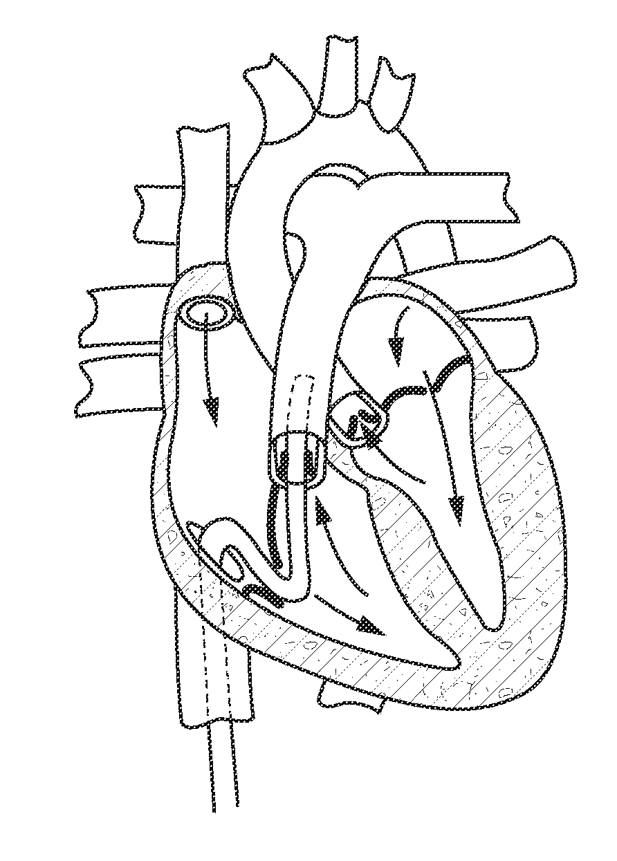
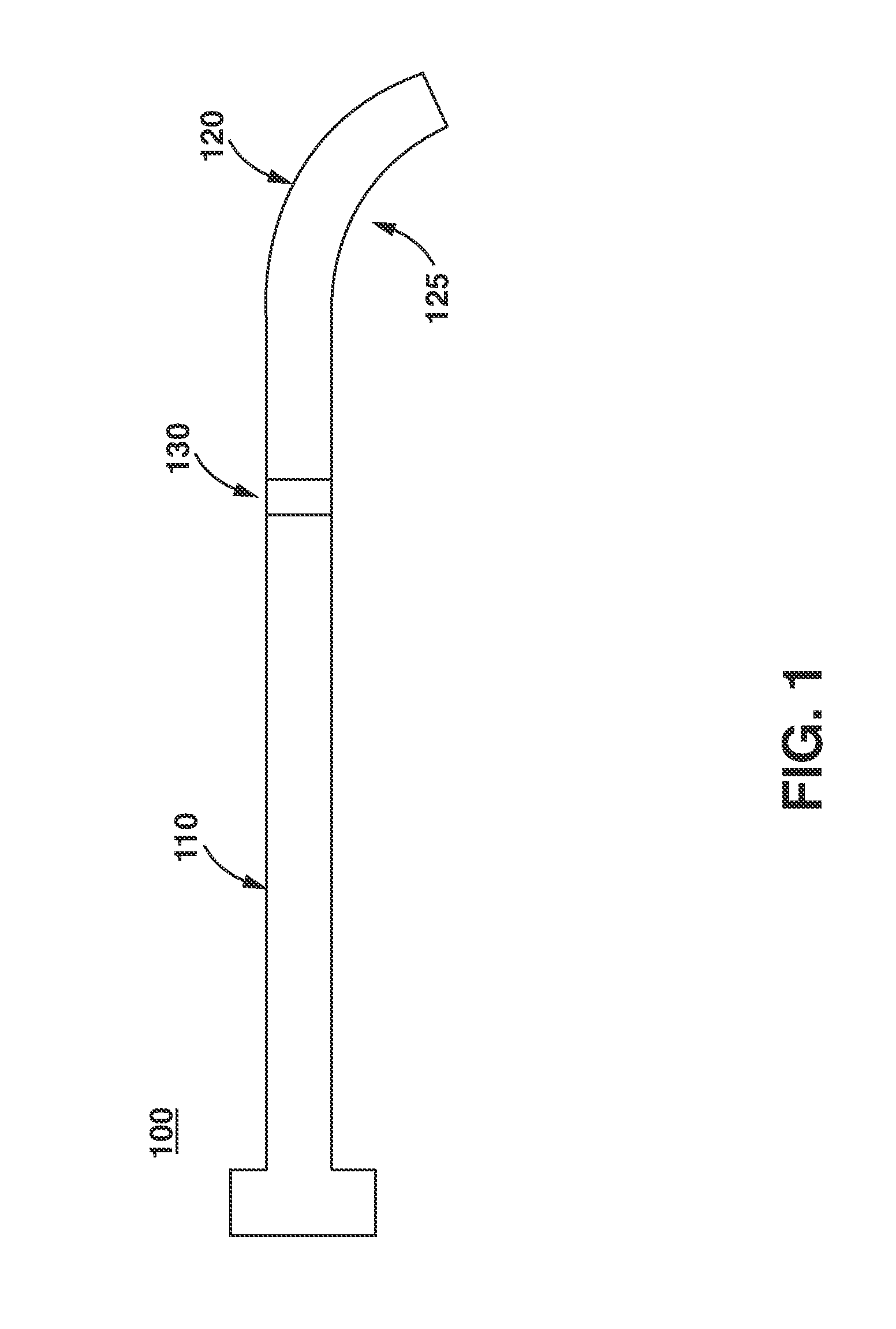
[0014]One aspect of the present invention is a catheter. One embodiment of the catheter, in accordance with the present invention, is illustrated in FIG. 1 at 100. Catheter 100 includes a proximal portion 110 and a distal portion 120. The distal portion 120 includes an arcuate portion 125. The arcuate portion 125 defines at least one radius such that there is no straight axis defined by the length of the arcuate portion 125. In one embodiment, each of the proximal portion 110 and distal portion 120 are integral and are not portions of the same structure.

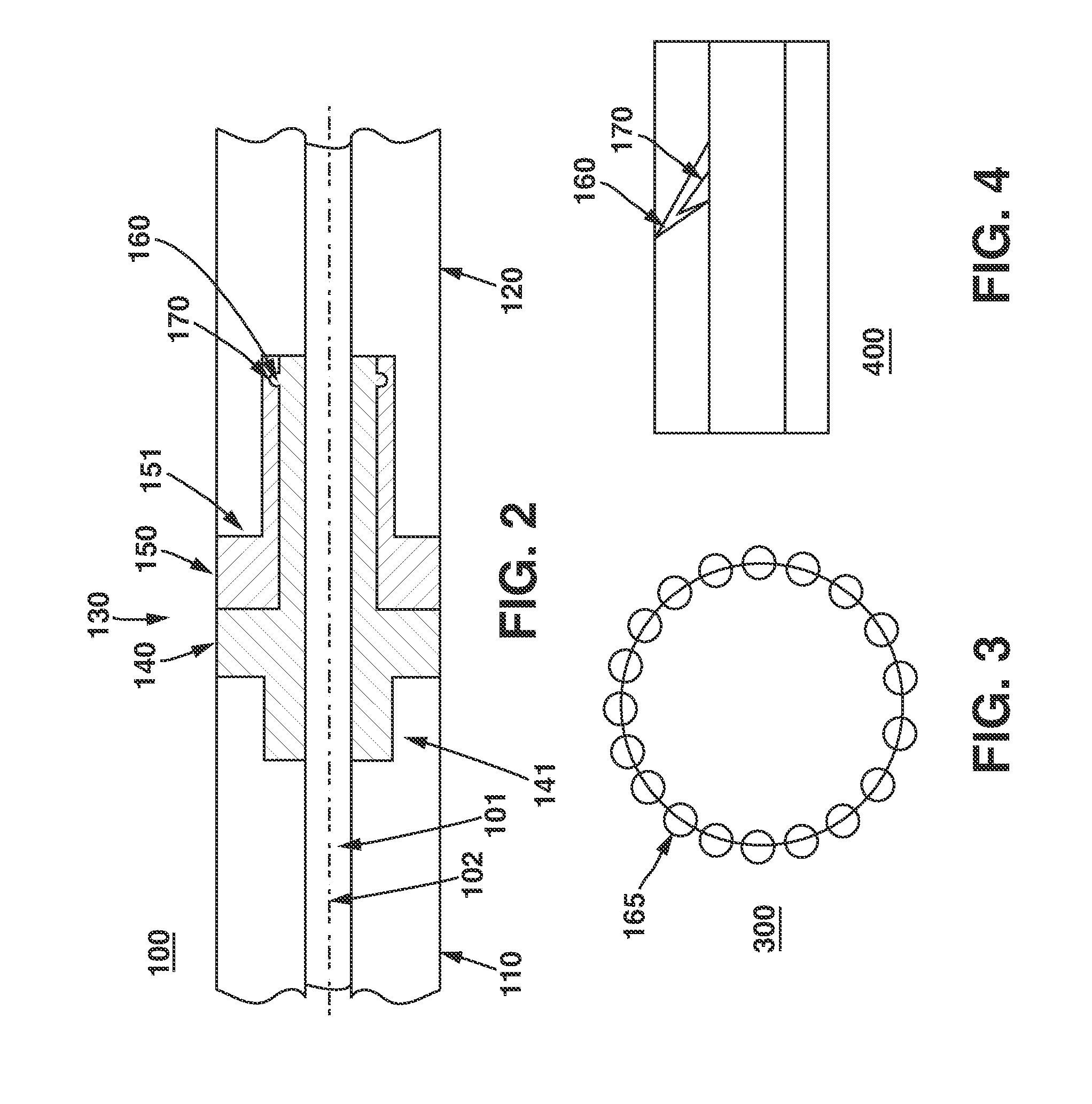
[0015]FIG. 2 illustrates aspects of the catheter 100 of FIG. 1 in greater detail. Specifically, catheter 100 includes a rotating portion 130. Rotating portion 130 connects the proximal portion and distal portion when catheter 100 is assembled. Rotating portion 130 includes a first piece 140 and a second piece 150. When assembled, first piece 140 and second piece 150 create a rotating snap fit. In one embodiment, each of the first pie...


PUM


Abstract

A catheter includes a proximal portion and a distal portion, the distal portion including an arcuate portion. The catheter further includes a rotating portion, the rotating portion connecting the proximal portion and distal portion, the rotating portion including a first piece and a second piece, wherein the first piece and second piece create a snap fit. Methods of using the catheter include threading the inserted catheter through the vasculature and allowing the distal portion to freely rotate about an axis defined by the rotating portion responsive to any tortuosity in the vasculature.

Description


Claims


Application Information

Patent Timeline
Owner MEDTRONIC VASCULAR INC
Why Eureka
Try Eureka