
Retainer system for electric cable couplers

a technology of electric cable couplers and cable retainers, which is applied in the direction of coupling device details, coupling device connections, coupling protective earth/shielding arrangements, etc., can solve the problems of inadvertent decoupling and “unplugging” and other problems, to prevent inadvertent decoupling and prevent inadvertent disruption of electric power. , to achieve the effect of preventing inadvertent decoupling

Active Publication Date: 2011-10-20
SIX SIGHTS CORP
View PDF9 Cites 82 Cited by
  • Summary
  • Abstract
  • Description
  • Claims
  • Application Information

AI Technical Summary

Benefits of technology

[0012]Preferably, the prongs have a beveled tip and are positioned relative to the loops so that merely pressing the male coupler into the female coupler (when the male retainer is attached to the male coupler and the female retainer is attached to the female coupler), causes the loops to pass over the prongs and “snap” past the prongs with the prongs residing within the loops. Once so snapped in place, the beveled surfaces on the prongs prevent removal of the loops off of the prongs, so that the male coupler remains securely attached to the female coupler. When removal of the male coupler from the female coupler is desired, forces can be applied to the levers on the male retainer so that the loops pivot (about arrow C) off of the prongs of the female retainer. The male coupler can then be removed from the female coupler. Inadvertent bumping or tugging on the male coupler or the cord associated with the male coupler will not be sufficient to inadvertently “unplug” the male coupler from the female coupler.
[0022]Another object of the present invention is to provide an electric cable coupling system which can more readily have a male coupler thereof inserted into a female coupler thereof than the male coupler can be removed from the female coupler.

Problems solved by technology

One problem with such couplers is that the plug mass of the male coupler fits within the female recess with some clearance space to facilitate the insertion of the male plug mass into the female recess.
Also, in data centers where it is critical that electrical equipment remain properly running continuously, it is essential that such electrical equipment not become “unplugged.” The clearance which allows the male coupler plug mass to fit within the recess in the female coupler creates the potential for inadvertent decoupling and “unplugging” to occur.

Method used


Image

  • Retainer system for electric cable couplers
  • Retainer system for electric cable couplers
  • Retainer system for electric cable couplers

Examples


Embodiment Construction

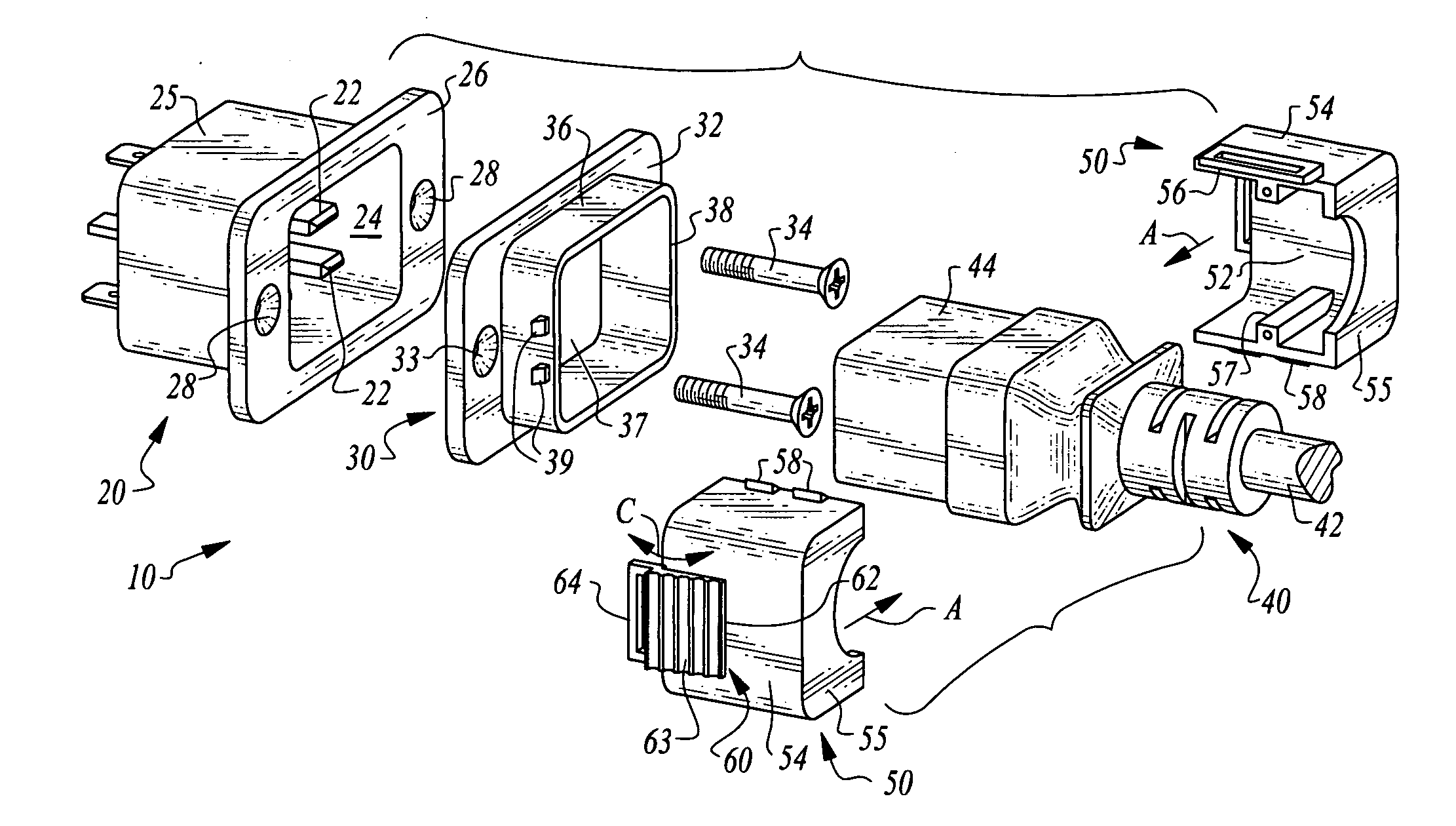
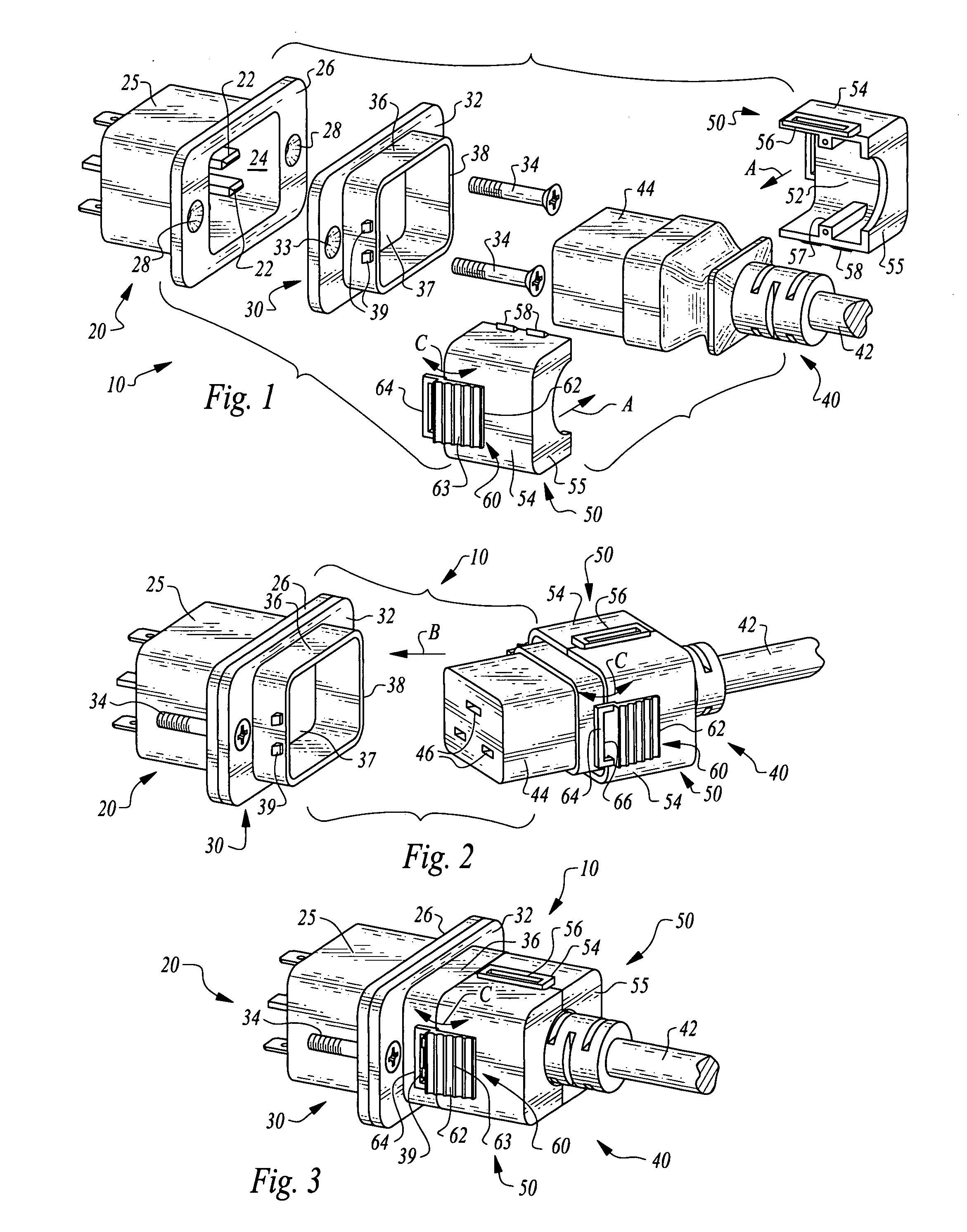
[0034]Referring to the drawings, wherein like reference numerals represent like parts throughout the various drawing figures, reference numeral 10 (FIGS. 1-3) is directed to a retainer system for retaining a female coupler 20 to a male coupler 40 defining terminal ends of electric cables 42 or other electric circuitry generally commonly referred to as electric cable according to this invention. The retainer system 10 in this first embodiment (FIGS. 1-3) is configured to have retainer portions removably attachable to the female coupler 20 and male coupler 40 so that the female coupler 20 and male coupler 40 do not need to be modified to benefit from the attributes of the retainer system 10 of this invention. An alternative retainer system 110 is depicted as well (FIGS. 26 and 27) where the retainer system 110 is built into the female coupler 120 and male coupler 140. A slightly modified second alternative retainer system 210 is also depicted exhibiting a different geometry from that ...


PUM


Abstract

Male and female couplers which are complementally formed to attach together are fitted with a retainer system including prongs on one of the couplers and a gap on the other of the couplers which can engage the prongs. The prong or gap is configured as either fixed or pivoting so that the pivoting portion can pivot to engage the fixed portion. When the male coupler is inserted into the female coupler, the prongs and gaps engage each other. To remove the male coupler from the female coupler, a pivoting portion must be pivoted to move the gap and prongs away from each other. The gap is configured as an at least partial recess into which the prong is received. The prongs and loop or slit are coupled to the male and female coupler ends through removably attachable male and female retainers or built directly into the female and male coupler.

Description

CROSS-REFERENCE TO RELATED APPLICATIONS[0001]This application claims benefit under Title 35, United States Code §119(e) of U.S. Provisional Application No. 61 / 342,955 filed on Apr. 20, 2010.FIELD OF THE INVENTION[0002]The following invention relates to couplers for the ends of electric power cables and cords which include a retainer feature to hold two complemental couplers together.BACKGROUND OF THE INVENTION[0003]Electric cables are often used with computer equipment or other appliances or other equipment that either runs off of electric power received through an electric power cable or which requires the transfer of signals along cables passing into or out of an electrically powered device. Such cables have a variety of different configurations to provide the required interconnections for transfer of power or signals into or out of such devices. The ends of such cables can generally be referred to as couplers. These couplers generally come in complemental male and female counterp...

Claims


Application Information

Patent Timeline
IPC IPC(8): H01R13/625
CPCH01R13/506H01R13/6273H01R13/6275H01R2103/00H01R24/22H01R24/70H01R13/652
Inventor CHEN, LIANG LIGHT
Owner SIX SIGHTS CORP
Features
  • Generate Ideas
  • Intellectual Property
  • Life Sciences
  • Materials
  • Tech Scout
  • Unparalleled Data Quality
  • Higher Quality Content
  • 60% Fewer Hallucinations
Learn More