Solid Food Product Container Dispenser

a technology for solid food products and dispensers, which is applied in the field of dispensers for solid food products, can solve the problems of not being easily accommodated in a conventional cup holder, the shape is generally relatively expensive, and so as to achieve the effect of greatly reducing the inability to take more than one solid food container at a tim

Active Publication Date: 2011-10-27
SAN JAMAR INC
View PDF9 Cites 1 Cited by
  • Summary
  • Abstract
  • Description
  • Claims
  • Application Information

AI Technical Summary

Benefits of technology

The present invention is a system and method for dispensing solid food product containers. It includes a shaped dispensing tube with support clips inside it for holding a stack of containers. The tube is mounted on a wall or other surface. The containers are fed into the tube until the bottom-most one engages with the clips. This results in the bottom-most container being positioned a predetermined distance below the tube. This design prevents more than one container from being taken at a time, making it more convenient for users.

Problems solved by technology

The technical problem addressed in this patent text is the need for a system and method to provide improved solid food product containers that overcome the limitations and drawbacks of current dispensing systems. Specifically, the patent aims to provide containers that can be easily and securely dispensed, while also being sanitary and preventing spillage. Additionally, the patent seeks to address the issue of multiple container dispensing and the need for a dispenser that can accommodate both standard drinking cup and elongated containers.

Method used


Image

  • Solid Food Product Container Dispenser
  • Solid Food Product Container Dispenser
  • Solid Food Product Container Dispenser

Examples


Embodiment Construction

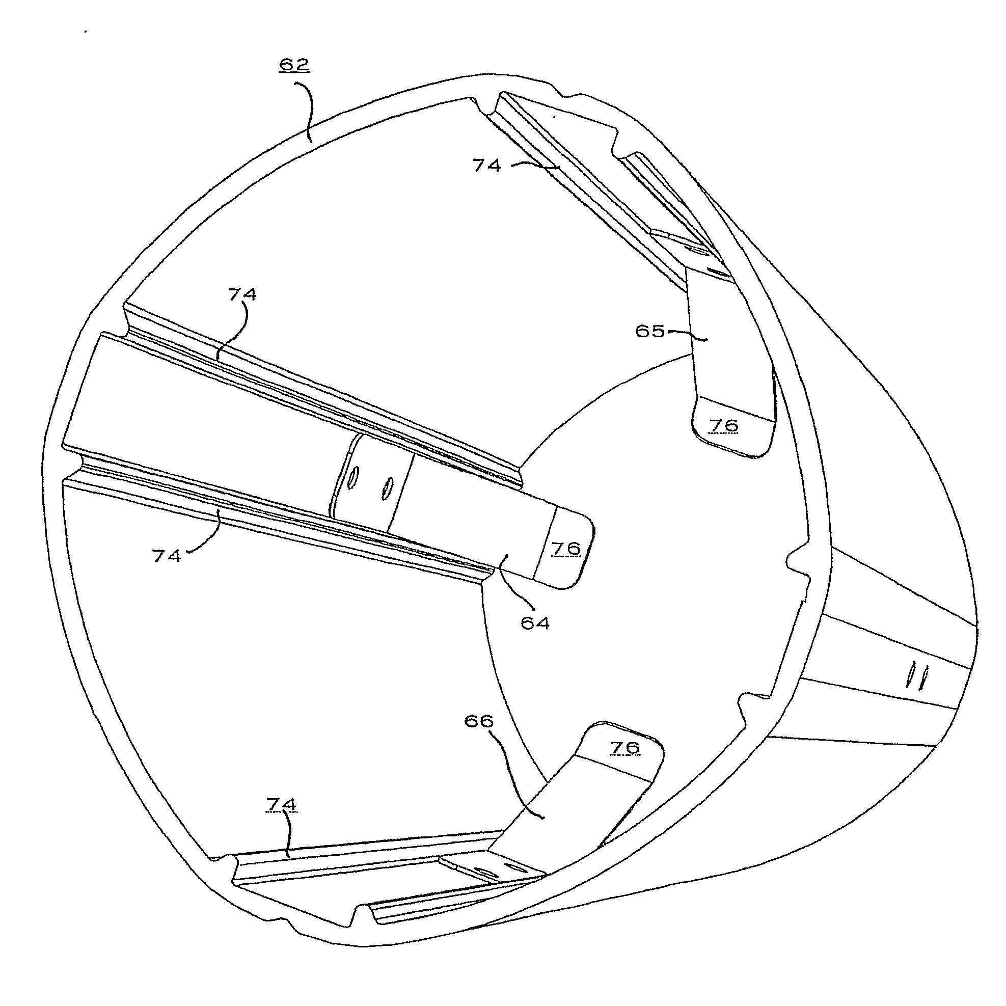
[0033]As shown in FIGS. 6-15, the dispenser 60 of the present invention includes a central tube 62 and a plurality of support clips 63, 64, 65 and 66. The dispenser 60 preferably also includes a bracket 68 for mounting the dispenser to a wall or the like (not shown).

[0034]The dispensing tube 62, as shown in FIGS. 7-9, is an irregular oval shape. Four clips 63, 64, 65 and 66 are placed substantially evenly around the tube 62. The clips are placed in channels 72 that are defined by longitudinal areas of increased thickness 74. While not necessary to the operation of the present invention, these areas of increased thickness provide increased stability, resistance to breakage and further define the interaction between a nested stack of solid food product containers 70 and the dispensing tube 62. The tube 62 is preferably made from polycarbonate to withstand the heat of the traditional French fry and other solid food preparation environments, but may be made of metal or any other rigid m...


PUM


Abstract

The present invention provides an improved system and method for dispensing solid food product containers. It comprises a shaped dispensing tube (62) of a predetermined length, having a plurality of support clips (76) arranged inside the dispensing tube (62) for holding a stack of solid food product containers (70) in place within the tube (62). The dispensing tube (62) preferably includes a bracket (68) for mounting the entire device on a wall or the like. A nested stack of containers (70) is fed into the preferably open top (78) of the dispensing tube (62) until the bottommost container engages (or is engaged by) the support clips (76). This results in the bottommost container extending a predetermined distance below the bottom of the dispensing tube (62). By minimizing the amount the bottommost container extends below the dispensing tube (62), a user's ability to take more than one solid food container at a time is greatly minimized.

Description


Claims


Application Information

Patent Timeline
Owner SAN JAMAR INC
Why Eureka
Try Eureka