
Sprockets for a flexible conveyor belt and conveyor belt system

a flexible conveyor belt and conveyor belt technology, applied in the direction of conveyors, transportation and packaging, etc., can solve the problems of not being ideally suited to use with flexible (non-modular) belts, the sprocket as described above suffers, and the sprocket of fig. 7a is not ideally suited to flexible (non-modular) belts. to achieve the effect of reducing the ability of the belt to buckl

Active Publication Date: 2015-04-07
HABASIT AG
View PDF39 Cites 6 Cited by
  • Summary
  • Abstract
  • Description
  • Claims
  • Application Information

AI Technical Summary

Benefits of technology

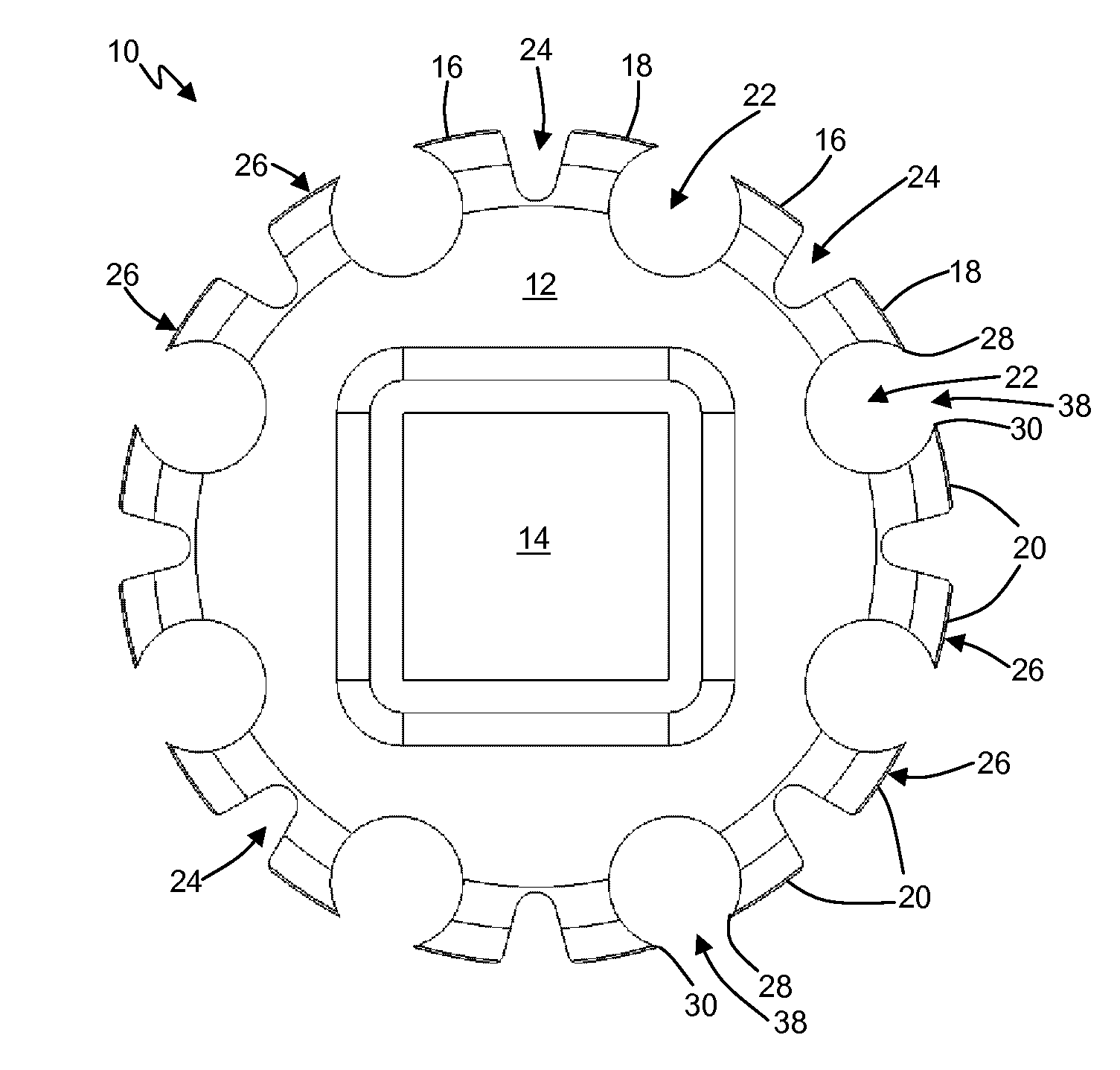
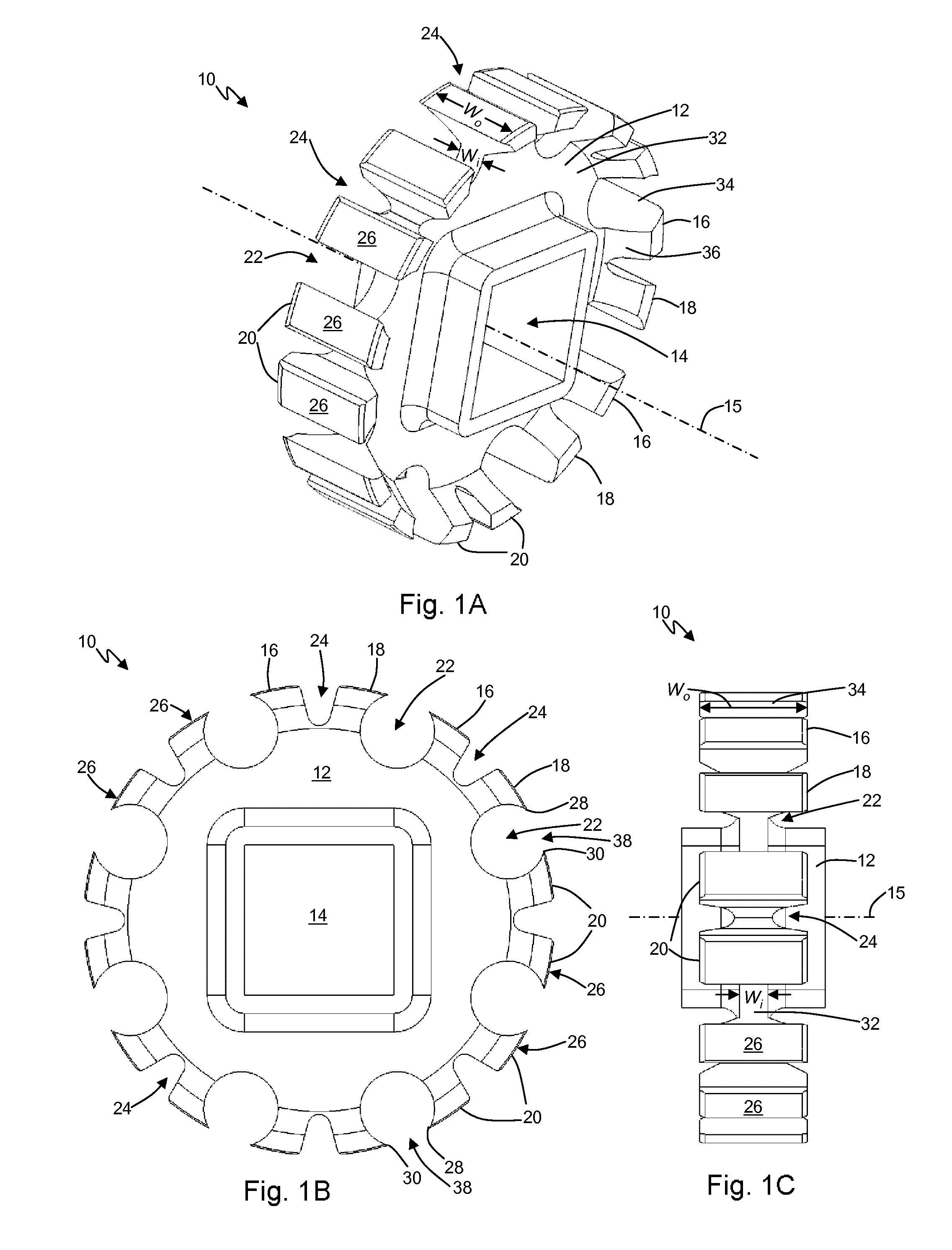
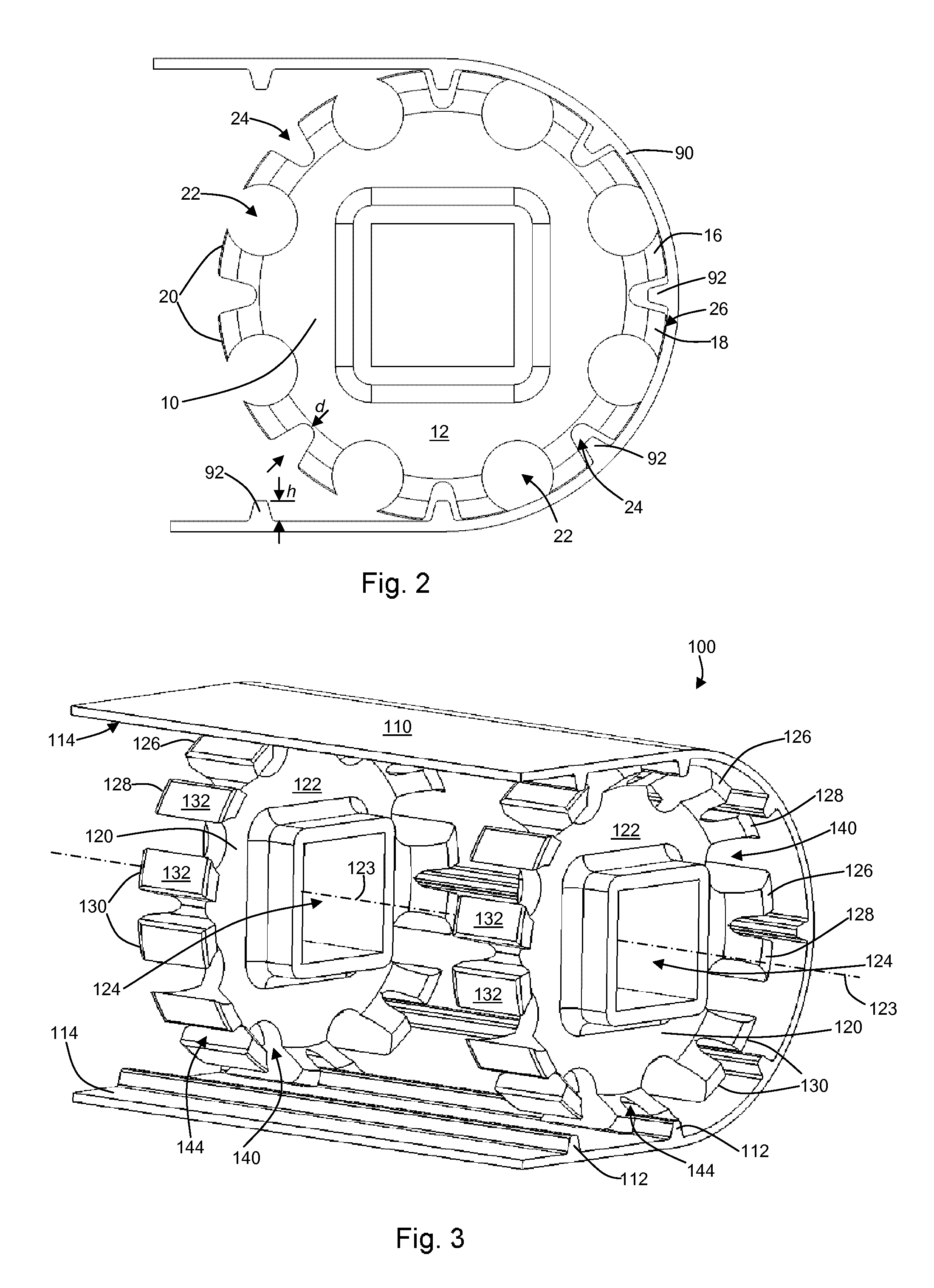
[0008]The present invention meets the above-described need by providing a sprocket having a body with a central opening for engaging a shaft and rotating about an axis. The sprocket has a plurality of teeth disposed around the periphery of the body. The teeth are angularly spaced about the axis such that each tooth is spaced from the adjacent teeth by a first opening. Each tooth has a belt-contacting surface which is convex in shape such that the outer-most periphery of the sprocket is generally circular. The belt-contacting surfaces of the teeth guide the belt around the periphery of the sprocket in order to minimize the ability of the belt to buckle.

Problems solved by technology

However, a sprocket as described above suffers from several disadvantages in environments where cleaning systems are used to maintain hygiene.
In this case, debris and contaminants are squeezed into the small gaps causing great difficulty in cleaning the affected areas.
Additionally, in many cases, two or more sprockets are used to engage a belt, and the above-described sprockets offer few options for passing cleaning fluid to the area between sprockets.
However, the sprocket of FIG. 7A is not ideally suited for use with flexible (non-modular) belts.
Over time, this buckling causes damage to the belt including cracks on the surface of the belt.

Method used


Image

  • Sprockets for a flexible conveyor belt and conveyor belt system
  • Sprockets for a flexible conveyor belt and conveyor belt system
  • Sprockets for a flexible conveyor belt and conveyor belt system

Examples


Embodiment Construction

[0028]Initially, it should be noted that the terms “belt,”“conveyor,”“conveyor belt,” and “flexible belt” are used interchangeably herein to refer to any non-modular belt as is known in the art. Such a belt may be constructed from fabrics coated by plastics or rubber, coated plastic sheets, monolithic plastic sheets, or other non-modular belt configurations. The terms may be used herein to refer to belts for any application, such as, for example, conveyor belts and process belts.

[0029]FIGS. 1A-1C depict a sprocket 10 according to an embodiment of the present invention. The sprocket 10 comprises a body 12 which may be constructed from stainless steel, plastic, or other suitable materials generally known to be food compatible and easily cleanable. The sprocket 10 includes a central opening 14 for engaging a shaft (not shown). The shaft may be a drive shaft. The central opening 14 may be shaped to cause the sprocket 10 to rotate as the shaft is rotated; for example, the central opening...


PUM


Abstract

A sprocket is provided, the sprocket having a body with a central opening for engaging a shaft and rotating about an axis. The sprocket has a plurality of teeth disposed around the periphery of the body. The teeth are angularly spaced about the axis such that each tooth is spaced from the adjacent teeth by a first opening. Each tooth has a belt-contacting surface which is convex in shape such that the outer-most periphery of the sprocket is generally circular. The belt-contacting surfaces of the teeth guide the belt around the periphery of the sprocket in order to minimize the ability of the belt to buckle.

Description

CROSS-REFERENCE TO RELATED APPLICATION[0001]The present application is a continuation-in-part of U.S. patent application Ser. No. 12 / 856,578 filed on Aug. 13, 2010, now abandoned the disclosure of which is incorporated herein by reference.FIELD OF THE INVENTION[0002]The present invention relates generally to conveyor belts, and more specifically to sprockets used to propel conveyor belts in environments where cleaning systems must be used to maintain hygiene.BACKGROUND OF THE INVENTION[0003]Traditional light conveyor belts are generally constructed from fabrics coated by plastics or rubber, or plastic sheets. In applications where hygiene and cleanliness are important, such as food processing plants, these conveyor belts are preferably made from monolithic plastics or otherwise sealed such that no contaminants can enter into the body of the belt, in order to prevent bacterial growth and other hygienic issues. Additionally, cleaning systems, which spray cleaning fluid on the sprocket...

Claims


Application Information

Patent Timeline
Patent Type & Authority Patents(United States)
IPC IPC(8): B65G23/06
CPCB65G23/06
Inventor LUCCHI, MARCO
Owner HABASIT AG
Learn More