Hydrodynamic separator for stormwater treatment

a technology of stormwater treatment and separator, which is applied in the field of advanced sediment removal devices, can solve the problems of pollution of our waterways, difficult identification of non-point sources, and significant adverse effects on the health of ecosystems, and achieve the effect of facilitating cleaning and maximizing access to the floor

Active Publication Date: 2019-03-14
BIO CLEAN ENVIRONMENTAL SERVICES
View PDF0 Cites 7 Cited by
  • Summary
  • Abstract
  • Description
  • Claims
  • Application Information

AI Technical Summary

Benefits of technology

[0008]The present invention accomplishes the above listed objectives by using a uniquely designed hydrodynamic separator including a flow splitter which redirects the flow of water upon entering the sump chamber from the inlet pipe. The flow splitter in combination with the oil-floatables skimmer minimizes the velocity of inflowing water and redirects it away from the center of the structure, which is generally round, and then along the structure's perimeter walls in two directions. Water flows along the walls and toward the oil-floatables skimmer on both sides. As these flows come in contact with the skimmer the flows continue along the skimmer wall back toward the center where the two flow paths flow into each other. At this point the flow paths are forced back toward the inlet from which they came. The two flow paths make a complete circle on the influent side of the oil-floatables skimmer. This creates a dual swirl action within the system and maximizes the flow path while keeping velocities low within the hydrodynamic separator, allowing for efficient capture and retention of trash, debris, and total suspended solids (TSS). Directing flows, containing sediments, especially finer sediment, back under the inlet which is as far away from the outlet as possible maximizes the ability of the system to capture and retain the finer sediments.
[0009]The outlet weir also plays a significant role in the system's performance. As with inlet velocities, outlet or exit velocities can also have a major impact on a systems overall effectiveness. During product development, different configurations were tested such as without an outlet weir, a shorter outlet weir and a taller outlet weir. A 6-inch tall outlet weir, measured from the outlet pipe invert proved to provide optimal performance. All weir configurations proved to be more effective than no outlet weir. In general, as water exits a structure and back into a pipe the velocity from the structure to the pipe quickly increases due the contraction of area into the pipe. This contraction creates a vacuum effect within the structure and can pull sediments out of the system that would have settled given more time and a condition of less velocity. To overcome this challenge, an outlet weir is placed across the outlet pipe. The outlet weir width is maximized within the system in order to spread the flow over it evenly. Because of the width of the weir is substantially wider than the pipe, the velocity of flow over the weir is minimized in a laminar fashion. This in turn increases the time particulates have to settle out on the effluent side of the oil-floatables skimmer. The weir also raises the water level in the system thus increasing the volume of water. The greater the volume of water within the system the more retention time. Studies have shown increased retention time also increases performance in particulate removal.
[0010]The present invention solves well know problems in the art such as short circuiting, minimal flow paths, minimal velocity reductions, inability to capture and retain finer sediments, floatables and oils / hydrocarbons. Other systems that employ velocity reduction and flow path maximization techniques do so without splitting the flow in two separate directions. This singular flow path has limited effectiveness as the velocity can only be reduced by the width of the structure in relation to inlet velocity. For example, a 2-foot pipe entering a 4-foot wide hydrodynamic separator can only reduce the velocity by half its inlet rate if flow distribution is perfectly even, which is known as laminar flow. A system that maximizes the flow path by directing all flows in one direction does not reduce the velocity of inflowing water thus minimizing its ability to capture finer particulates. Since the present invention splits the influent flow velocity in half its performance in capturing finer particulates is increased.

Problems solved by technology

The volume and flow rate of stormwater runoff is a concern because large volumes and high flow rates can cause erosion and flooding.
Pollution and contamination of stormwater runoff is a concern because stormwater runoff flows into our rivers, streams, lakes, wetlands, and / or oceans.
Pollution and contamination carried by stormwater runoff into such bodies of water can have significant adverse effects on the health of ecosystems.
Non-point sources are more difficult to identify.
Studies have revealed that contaminated stormwater runoff is the leading cause of pollution to our waterways.
As more land becomes impervious, less rain seeps into the ground, resulting in less groundwater recharge and higher velocity flows, which cause erosion and increased pollution levels of watery environments.
When land is stripped of vegetation, stormwater runoff erodes the exposed land and carries it into storm drains.
These organic substances leach out large amounts of nutrients as they decompose and cause large algae blooms, which deplete dissolved oxygen levels in marine environments and result in expansive marine dead zones.
Heavy metals that come from numerous sources are harmful to fish, wildlife, and humans.
Many of our waterways are no longer safe for swimming or fishing due to heavy metals introduced by stormwater runoff.
These pollutants come from leaky vehicles and other heavy equipment that use hydraulic fluid, brake fluid, diesel, gasoline, motor oil, and other hydrocarbon based fluids.
Bacteria and pesticides are additional harmful pollutants carried into waterways by stormwater runoff.

Method used


Image

  • Hydrodynamic separator for stormwater treatment
  • Hydrodynamic separator for stormwater treatment
  • Hydrodynamic separator for stormwater treatment

Examples


Embodiment Construction

[0036]After reading this description it will become apparent to one skilled in the art how to implement the invention in various alternative embodiments and alternative applications. However, all the various embodiments of the present invention will not be described herein. It is understood that the embodiments presented here are presented by way of an example only, and not limitation. As such, this detailed description of various alternative embodiments should not be construed to limit the scope or breadth of the present invention as set forth below.

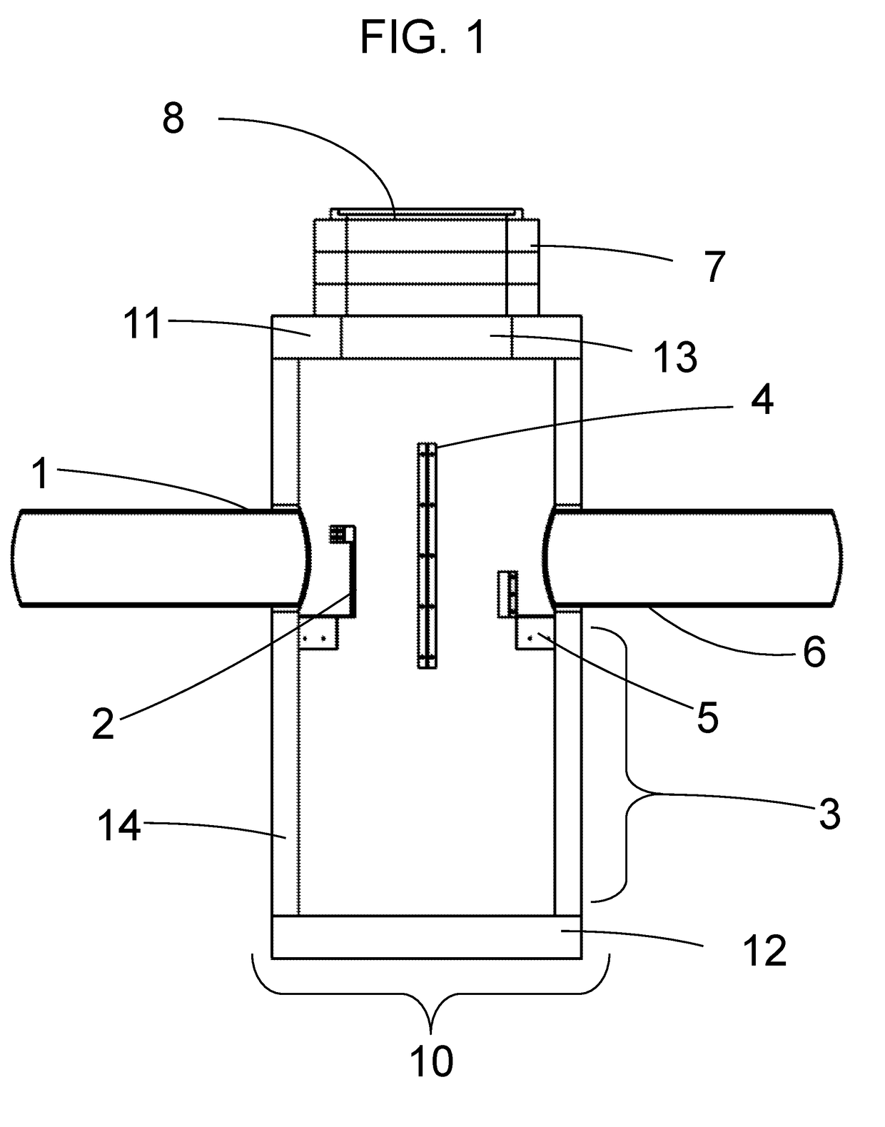
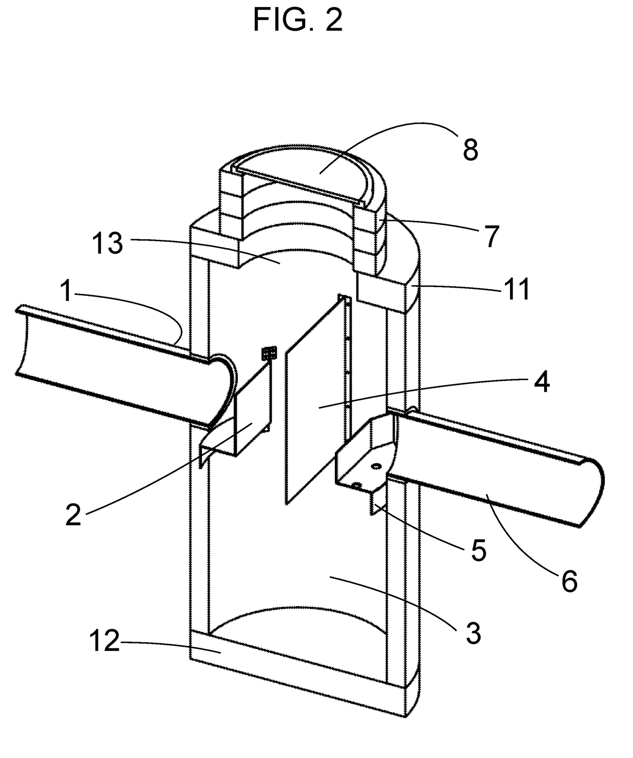
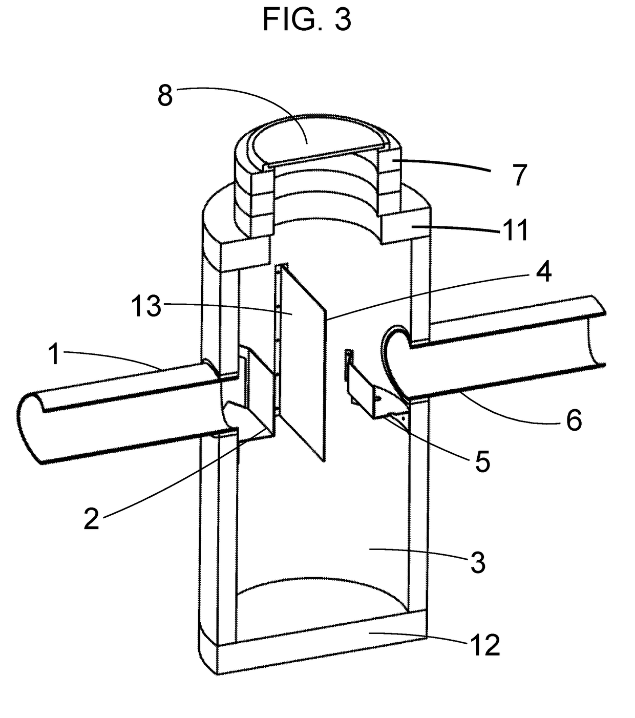
[0037]The present invention provides an improved hydrodynamic separator 10 for stormwater treatment designed to maximize flow movement for more efficient sediment removal from stormwater and to maximize clearance space within the sump chamber to facilitate cleaning and increase storage capacity of trash, debris, and sediment.

[0038]In some embodiments, configurations of said invention can be customized depending on site needs, government...


PUM

PropertyMeasurementUnit
diameteraaaaaaaaaa
diameteraaaaaaaaaa
thicknessaaaaaaaaaa

Abstract

A method, system, and apparatus directed to an innovative approach for the treatment of stormwater utilizing hydrodynamic separator assembly designed to maximize flow movement for more efficient sediment removal and maximize clearance space within assembly to facilitate cleaning and increase storage capacity of trash, debris, and sediment.

Description

FIELD OF THE INVENTION[0001]The embodiments of the present technology relate in general to an advanced sediment removal devices based on principles of hydrodynamic and gravity separation. More specifically, a hydrodynamic separator to remove sediments and other pollutants from polluted stormwater runoff and polluted water sources. The hydrodynamic separator is designed to reduce velocity and maximize flow path within a settling chamber of minimal size to maximize performance and feasibility. The hydrodynamic separator is generally installed subsurface within the drainage infrastructure of various private and public drainage systems.BACKGROUND AND PRIOR ART[0002]Water treatment systems have been in existence for many years. These systems treat stormwater surface runoff or other polluted water. Stormwater runoff is of concern for two main reasons: i. volume and flow rate, and ii. pollution and contamination. The volume and flow rate of stormwater runoff is a concern because large volu...

Claims


Application Information

Patent Timeline
Patent Type & Authority Applications(United States)
IPC IPC(8): E03F5/14B01D21/00
CPCE03F5/14B01D21/0024B01D21/0087B01D17/0211B01D21/0012B01D2221/12B01D21/2405B01D21/0039B01D21/0003B01D21/0006B01D21/0042B01D21/2433B01D21/2444B01D21/245
Inventor KENT, ZACHARIHA J.
Owner BIO CLEAN ENVIRONMENTAL SERVICES
Why Eureka
Try Eureka