Boat storage stacker with rotatable and offset mast

Active Publication Date: 2017-08-29
MAFFETT BRIAN
View PDF11 Cites 0 Cited by
  • Summary
  • Abstract
  • Description
  • Claims
  • Application Information

AI Technical Summary

Benefits of technology

[0018]Additionally, the system is configured such that the footprint of the rotating structure is large enough to accommodate the center of gravities of the unloaded and loaded system but is of a size that is practical given the space constraints of typical dry storage facilities. It is typically the diameter of the rotating structure within the dry storage facilities that dictates the overall footprint of the crane system and the watercraft storage facility as a whole. Additionally, the system can minimize the momentum forces created, or developed, when moving loads at speeds, accelerations and decelerations. These forces will preferably be reduced, or conversely the speeds can be increased during operation, with the current center of gravity of the system being balanced about the cent

Problems solved by technology

This is different from conventional cranes that use rotating bearings that can fail and allow the mast and load to break fre

Method used


Image

  • Boat storage stacker with rotatable and offset mast
  • Boat storage stacker with rotatable and offset mast
  • Boat storage stacker with rotatable and offset mast

Examples


Embodiment Construction

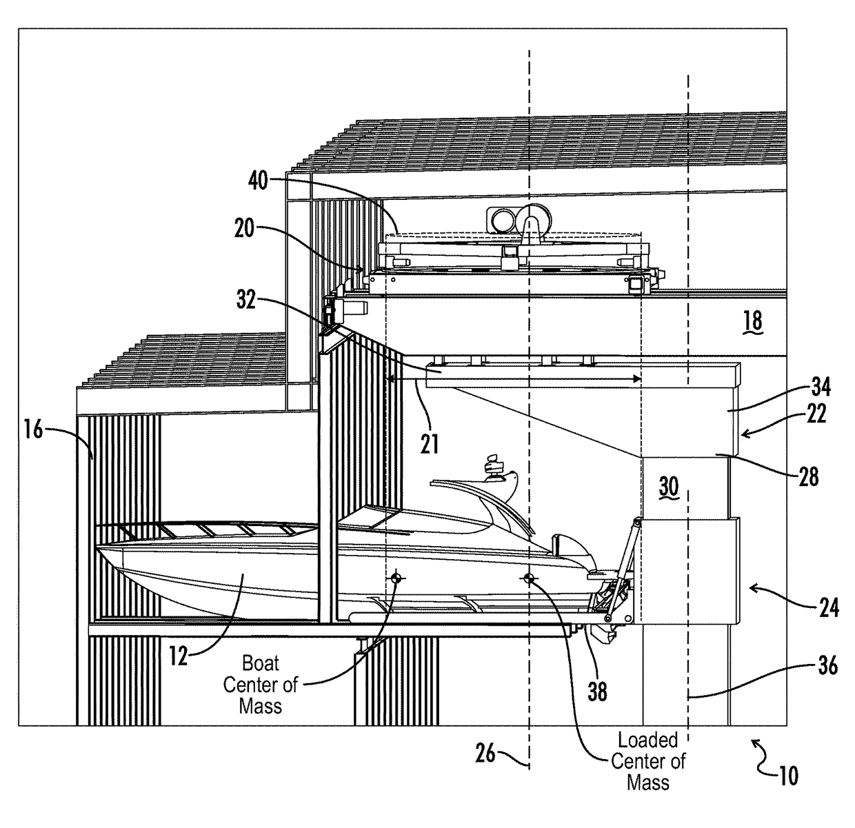
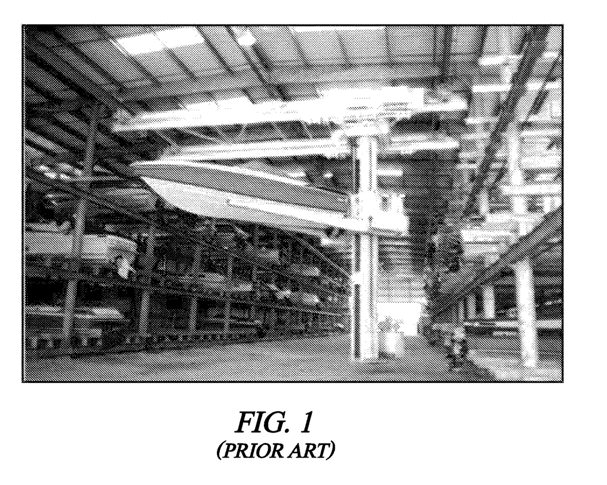
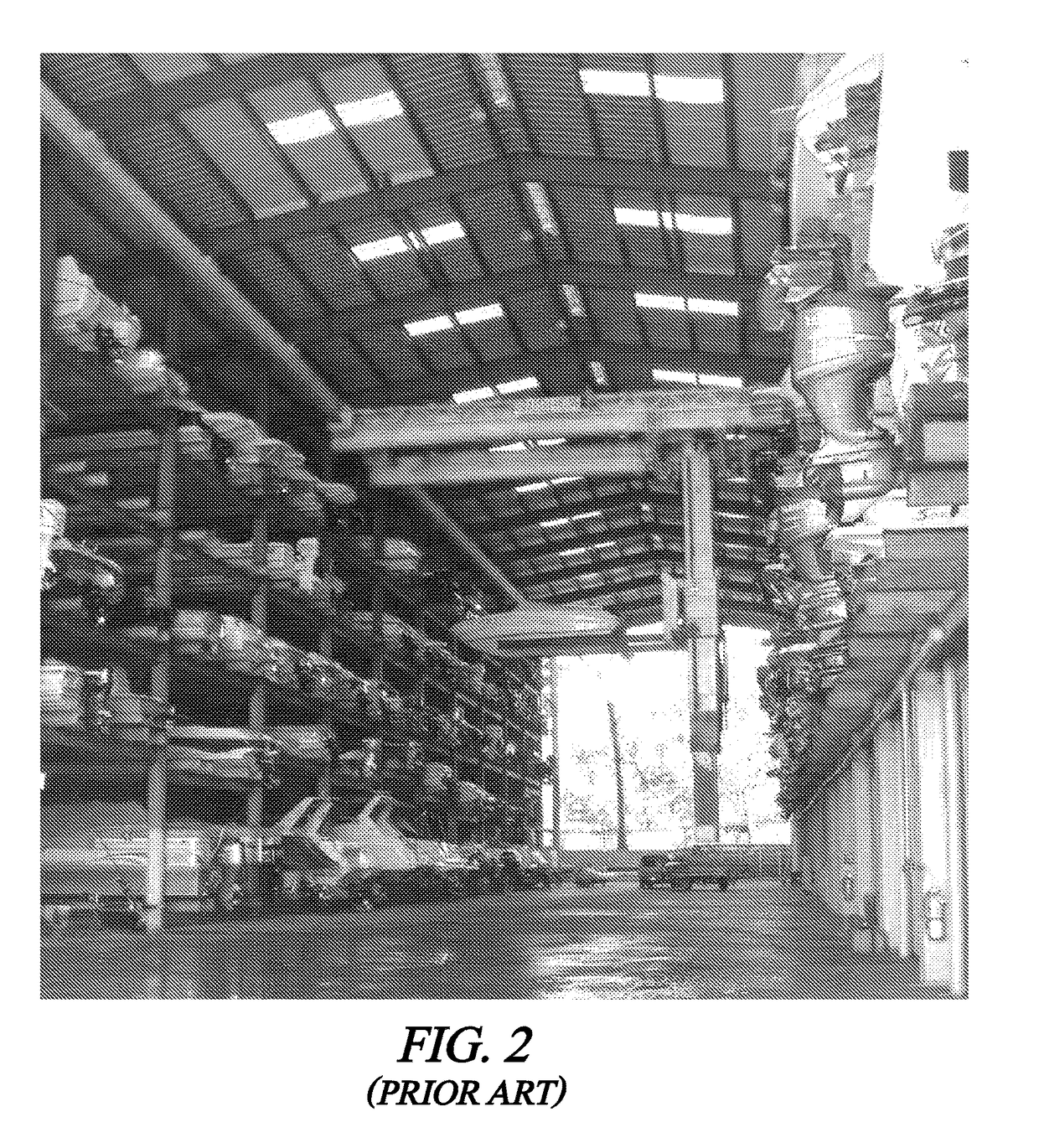
[0034]Referring generally now to FIGS. 1-3 prior art stacker cranes have included center of gravities that fall outside the footprint of the turning device. This is especially true when the stacker cranes are loaded with a water craft as shown in FIGS. 1 and 2. In these images, as explained graphically in FIG. 3, the loading of the water craft, and its center of gravity, takes the overall center of gravity of the water craft and the conventional stacker crane assembly outside the footprint of the rotating device. As previously mentioned this puts a large amount of strain on the rotating device, mast, and overall stacker crane assembly. This strain either causes premature failure in this stacker crane assembly or mandates large expensive devices that are over engineered in order to counteract this center of gravity phenomenon that occurs outside the turning device footprint.

[0035]Referring now generally to FIGS. 4-13, a stacker crane is shown and generally designated by the numeral 1...


PUM


Abstract

Disclosed herein is a watercraft storage stacker crane system that incorporates an offset mast.

Description

[0001]This is a non-provisional patent application claiming priority to U.S. Provisional Patent Application Ser. No. 61 / 800,675 filed Mar. 15, 2013 and entitled “Boat Storage Stacker with Rotatable and Offset Mast”.[0002]This non-provisional patent application is filed by Brian Maffett, a citizen of the United States, residing at 231 East Broad Street, Suite 102, Cookeville, Tenn. 38501, for the invention of a “Boat Storage Stacker with Rotatable and Offset Mast.”[0003]A portion of the disclosure of this patent document contains material that is subject to copyright protection. The copyright owner has no objection to the reproduction of the patent document or the patent disclosure, as it appears in the U.S. Patent and Trademark Office patent file or records, but otherwise reserves all copyright rights whatsoever.[0004]All patents and publications described or discussed herein are hereby incorporated by reference in their entirety.BACKGROUND OF THE INVENTION[0005]The present disclosu...

Claims


Application Information

Patent Timeline
IPC IPC(8): B63C3/12B63C15/00
CPCB63C3/12B63C15/00
Inventor MAFFETT, BRIAN
Owner MAFFETT BRIAN
Why Eureka
Try Eureka