Devices, Assemblies, and Methods for Controlling Fluid Flow

a technology of fluid flow and devices, applied in the direction of fluid cut-off devices, joints, infusion syringes, etc., can solve the problems of high manufacturing cost and ineffectiveness of conventional devices and assemblies for establishing medical connections

Active Publication Date: 2011-11-03
INFUSION INNOVATIONS
View PDF13 Cites 54 Cited by
  • Summary
  • Abstract
  • Description
  • Claims
  • Application Information

AI Technical Summary

Benefits of technology

[0011]Conventional devices and assemblies for establishing medical connections are not completely effective and are potentially unsafe. For example, conventional medical connectors may expose the user to harmful agents during disconnection as a result of undesired bolus effects, may collect undesired fluid within their internal volumes after disconnection, may not notify the user of the actuation status during connection and disconnection, and / or may include many parts thereby making manufacture expensive. In contrast, embodiments herein may use fewer parts, may minimize and / or eliminate residual fluid within the connectors after disconnection, may utilize a rotational actuation force as opposed to translation force to avoid or create a desired bolus effect, and / or may incorporate actuation status indicators to notify the user when actuation is complete.
[0015]The tubular member may be disposed within the inner housing and may include a fluid passage therein extending between the second end of the outer shell and the boss of the inner housing. The tubular member may be carried by the inner housing such that the tubular member moves axially as the inner housing moves between the first and second positions. The connector assembly may also include cam features on the outer shell and / or the tubular member for causing the tubular member to rotate as the inner housing moves between the first and second positions, thereby opening a fluid path between the fluid passage in the tubular member and the first end of the outer shell.
[0017]In accordance with another embodiment, a connector and / or valve assembly is provided for controlling flow in a fluid line that includes an outer shell including a first end, a second end, and a passage extending therebetween, the first end including a connector for connecting the assembly to a fluid line; an inner housing disposed within the outer shell and including a boss disposed adjacent the first end, the inner housing being movable axially within the outer shell between a first position adjacent the first end and a second position further from the first end than the first position when a device is connected to the connector on the first end of the outer shell; a tubular member disposed within the inner housing and including a fluid passage therein extending between the second end of the outer shell and the boss of the inner housing, the tubular member carried by the inner housing such that the tubular member moves axially as the inner housing moves between the first and second positions; and cam features on the inner housing and the tubular member for causing the tubular member to rotate as the inner housing moves between the first and second positions, thereby opening a fluid path between the fluid passage in the tubular member and the first end of the outer shell to allow fluid flow through the assembly with the device connected to the first end of the outer shell.
[0018]In accordance with another embodiment, a connector assembly for controlling flow in a fluid line is provided that includes an outer shell or bezel including a first end, a second end, and a passage extending therebetween, the first end including a connector for connecting the assembly to a fluid line. An inner housing may be disposed within the outer shell that includes a boss disposed adjacent the first end, the inner housing being movable axially within the outer shell between a first position adjacent the first end and a second position further from the first end than the first position when a device is connected to the connector on the first end of the outer shell. A backing member may be coupled to the second end of the outer shell such that the outer shell is substantially axially fixed relative to the backing member and rotatable relative to the backing member, the backing member slidably coupled to the inner housing such that the inner housing moves helically relative to the backing member when the inner housing is directed from the first position towards the second position. A tubular member may include a first end disposed within the inner housing and a second end extending through the backing member, the tubular member slidably coupled to the backing member such that the tubular member substantially rotationally fixed relative to the backing member and is movable axially relative to the backing member, the tubular member comprising a fluid passage therein extending between the first and second ends. A seal on the boss may engage the first end of the tubular member in the first position to substantially seal the fluid passage, and cam features may be provided on the inner housing and the tubular member for coupling axial movement of the tubular member to axial movement of the inner housing when the inner housing is initially moved from the first position towards the second position, the cam features causing the tubular member to move distally relative to the inner housing immediately before the inner housing reaches the second position, thereby disengaging the seal from the first end of the tubular member and opening the fluid passage.

Problems solved by technology

Conventional devices and assemblies for establishing medical connections are not completely effective and are potentially unsafe.
For example, conventional medical connectors may expose the user to harmful agents during disconnection as a result of undesired bolus effects, may collect undesired fluid within their internal volumes after disconnection, may not notify the user of the actuation status during connection and disconnection, and / or may include many parts thereby making manufacture expensive.

Method used


Image

  • Devices, Assemblies, and Methods for Controlling Fluid Flow
  • Devices, Assemblies, and Methods for Controlling Fluid Flow
  • Devices, Assemblies, and Methods for Controlling Fluid Flow

Examples


Embodiment Construction

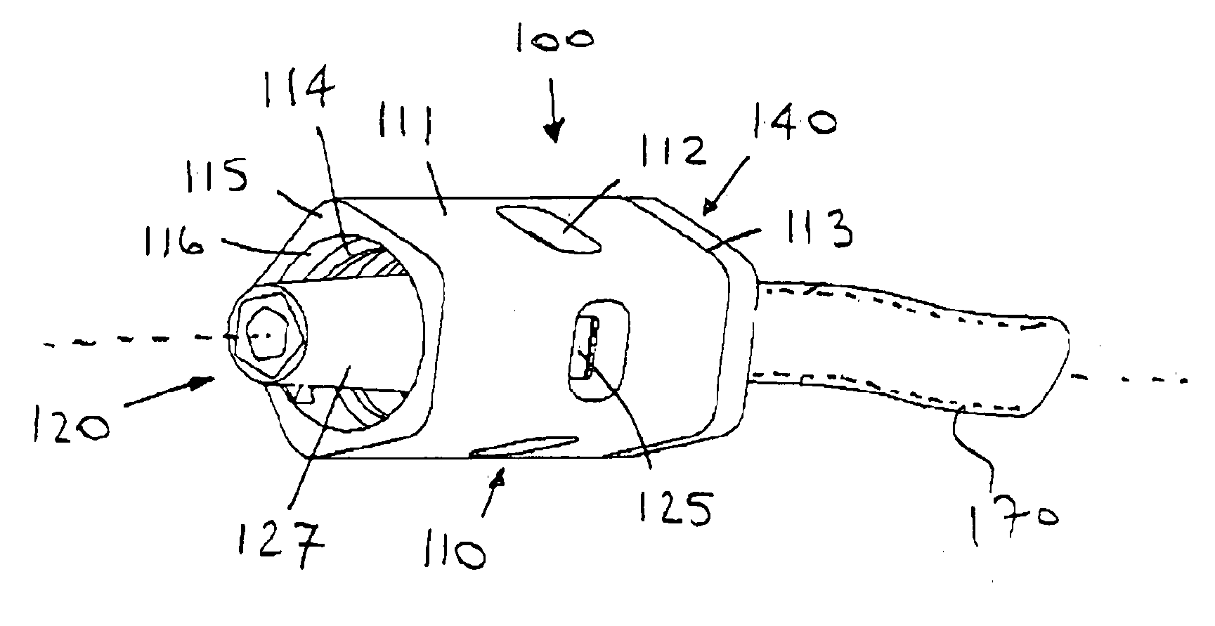
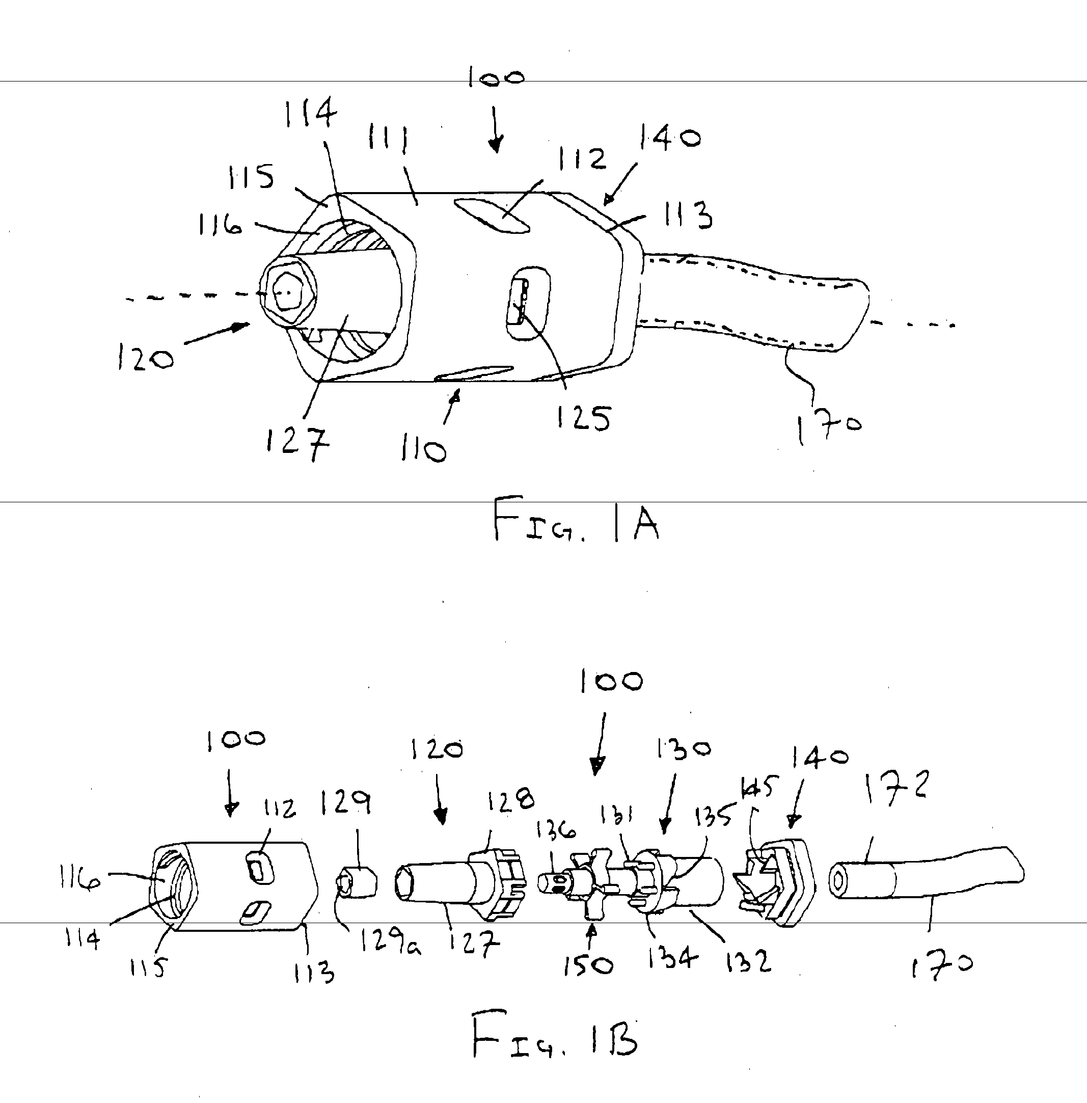
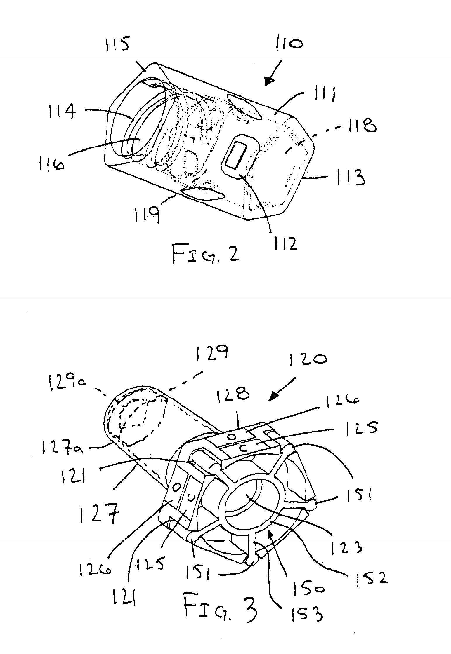
[0103]Apparatus and methods described herein may relate to connecting devices and assemblies that, among other things: utilize a rotational force for actuation to avoid or create a desired bolus effect, minimize the number of parts necessary for manufacture, decrease the internal volume of the devices and assemblies, and / or use status indicators to signify when actuation and deactuation are complete. Also, in some embodiments, the apparatus described herein may create and maintain a flat (planar) surface that is easily swabbed for cleaning and sterilization purposes. Although embodiments of connecting devices and assemblies are described herein with respect to medical connections, such connecting devices and assemblies are not limited to medical connections alone but may be applicable to any connection device or assembly that could benefit from the use of a rotational actuation force, status indicators, and / or any of the other features described herein.

[0104]For the following descri...


PUM


Abstract

Connector assemblies are provided for controlling flow in a fluid line that include an outer shell, an inner housing, and a tubular member. The inner housing is disposed within the outer shell and includes a boss disposed adjacent a first end of the outer shell. The inner housing is movable axially within the outer shell between first and second positions when a device is connected to the first end. The tubular member is carried by the inner housing and includes a fluid passage extending between a second end of the outer shell. The tubular member moves axially as the inner housing moves between the first and second positions, and cam features on the outer shell and the tubular member cause the tubular member to rotate as the inner housing moves between the first and second positions, thereby opening a fluid path between the fluid passage and the first end.

Description

FIELD OF THE INVENTION[0001]The present invention relates generally to apparatus and methods for controlling flow. More particularly, the present invention relates to devices, assemblies, and / or methods for controlling fluid flow, e.g., to connectors and / or valves for controlling flow through an IV or other fluid line into a patient, a syringe, container, and / or other medical device, and / or to systems including such connectors and / or valves.BACKGROUND[0002]Controlling flow is an important and useful tool in virtually all scientific fields. One such field where controlling flow is highly useful is in the medical arena. For example, it may be useful to control flow during infusion, e.g., when introducing fluid into a blood vessel, such as a vein, via a fluid line for therapeutic and / or diagnostic purposes. The fluid introduced may be saline solution, plasma solution, glucose solution, antibiotics, pain relievers, nuclear medicine agents, and the like. Infusion may involve many fluid d...

Claims


Application Information

Patent Timeline
Patent Type & Authority Applications(United States)
IPC IPC(8): F16L29/00
CPCA61M5/16881A61M39/10A61M39/26A61M2039/263A61M39/12A61M2039/1033A61M5/16813A61M2039/268A61M5/178A61M39/20A61M2039/1038A61M2039/1066A61M2205/6018
Inventor STROUP, DAVID K.
Owner INFUSION INNOVATIONS
Why Eureka
Try Eureka