Devices, assemblies and methods for controlling fluid flow

a technology of fluid flow and apparatus, applied in the direction of intravenous devices, medical syringes, valves, etc., can solve the problems of increasing the potential for bruising, affecting the patient's recovery, and causing pain or discomfort to the patient, so as to reduce the residual fluid within the connector and eliminate the effect of residual fluid

Active Publication Date: 2013-12-10
INFUSION INNOVATIONS
View PDF15 Cites 16 Cited by
  • Summary
  • Abstract
  • Description
  • Claims
  • Application Information

AI Technical Summary

Benefits of technology

[0012]The present invention is directed to apparatus and methods for controlling flow through a fluid line or device, for example, to connectors and / or valves for delivering fluid via an intravenous (“IV”) or other medical fluid line into a patient, a syringe, container, and / or other medical device, and to systems including such connectors and / or valves. Embodiments described herein may use fewer parts than conventional fluid flow devices for delivering fluid via a medical fluid line, may minimize and / or eliminate residual fluid within the connectors after disconnection, may utilize a rotational actuation force as opposed to translation force to avoid or create a desired bolus effect, and / or may incorporate actuation status indicators to notify the user when actuation is complete.
[0030]In a further embodiment, the valve assembly includes a second or distal end that extends distal of tip when the valve assembly is in the closed condition and an outer shell includes one or more windows to view a colored band or end portion indicator, which becomes exposed as the inner housing moves into the extended, open position, to determine when the valve assembly is in an actuated or open condition. The second end extends distal of tip when the valve assembly is in the closed condition to prevent the tip from being contaminated.
[0031]In a still further embodiment, the valve assembly includes a peel away seal (e.g., peel away tamper foil) adhered to a distal end to further prevent the tip of the valve assembly from being contaminated.
[0032]In an additional embodiment, the valve assembly may include a disinfectant media disposed on and / or around the tip within inner housing. Through movement of the valve assembly components, connection of Luer assembly, and / or other means, the disinfectant media disinfects the tip, further preventing the tip from being contaminated.

Problems solved by technology

Repeated insertion of a needle into the same vein of a patient, however, may damage the vein, increase the potential for bruising, and / or inflict pain on or discomfort to the patient.
Once inserted into the patient's vein, the stationary needle could be secured with tape, but was prone to disconnection from the patient.
This method relieved some of the disconnection problems, but a new problem emerged.
These small amounts of blood would accumulate in the catheter, thereby clogging the fluid pathway.
The replacement of these clogged catheters may be expensive and / or painful to the patient.
As mentioned above, for certain applications, the fact that residual volume of the fluid may be unsealed and / or exposed to individuals around the IV system may pose significant health hazards.
Additionally, these conventional Luer connectors may have a larger internal volume in which fluid may collect, and also employ many parts thereby increasing the potential for error in manufacturing or during use.
Thus, the user may not know at what point the fluid path is sufficiently opened or closed during connection and disconnection of the two connectors.
Conventional devices and assemblies for establishing medical connections are not completely effective and are potentially unsafe.
For example, conventional medical connectors may expose the user to harmful agents during disconnection as a result of undesired bolus effects, may collect undesired fluid within their internal volumes after disconnection, may not notify the user of the actuation status during connection and disconnection, and / or may include many parts thereby making manufacture expensive.

Method used


Image

  • Devices, assemblies and methods for controlling fluid flow
  • Devices, assemblies and methods for controlling fluid flow
  • Devices, assemblies and methods for controlling fluid flow

Examples


Embodiment Construction

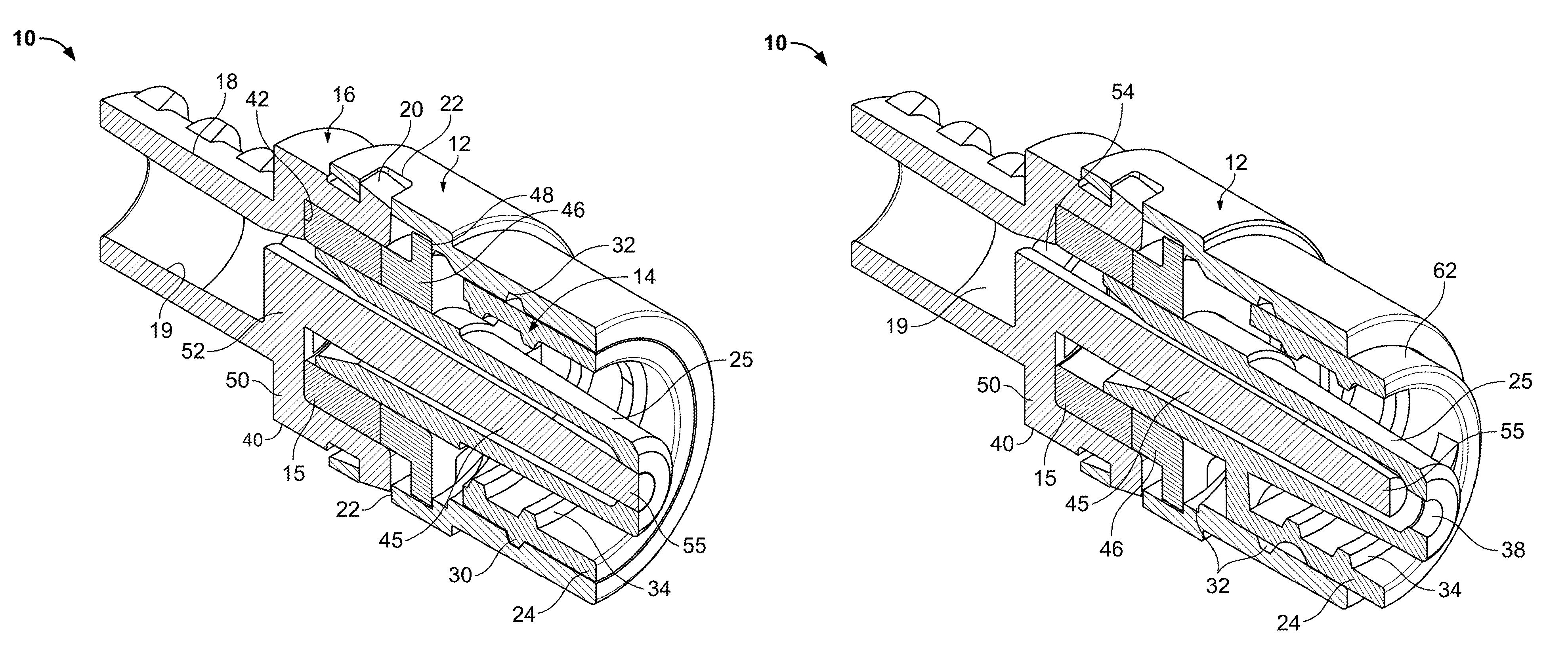
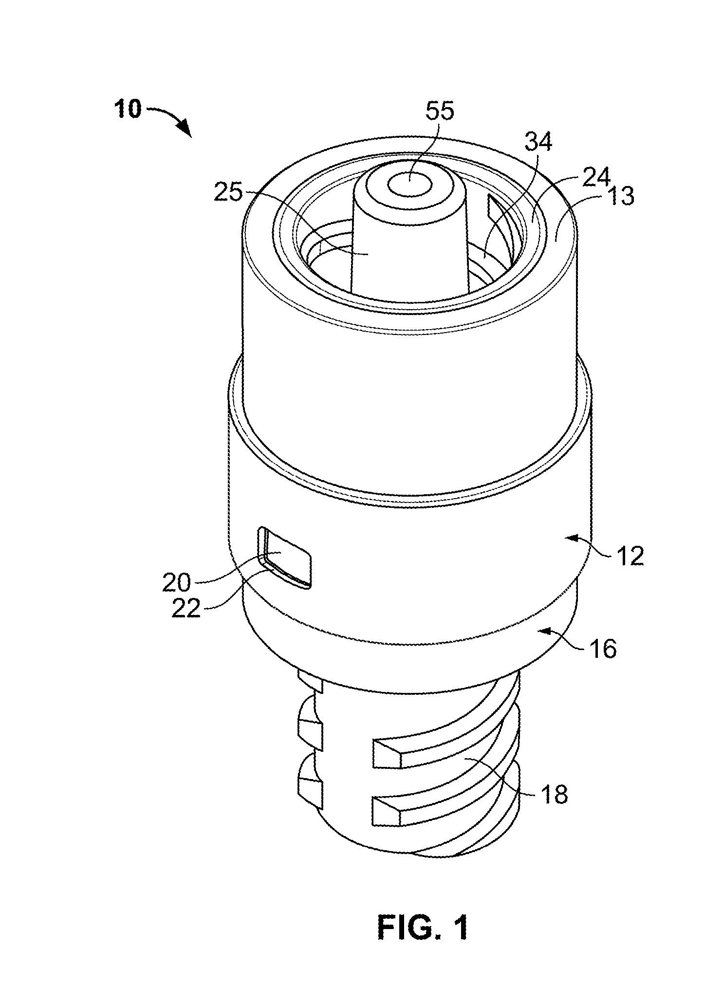
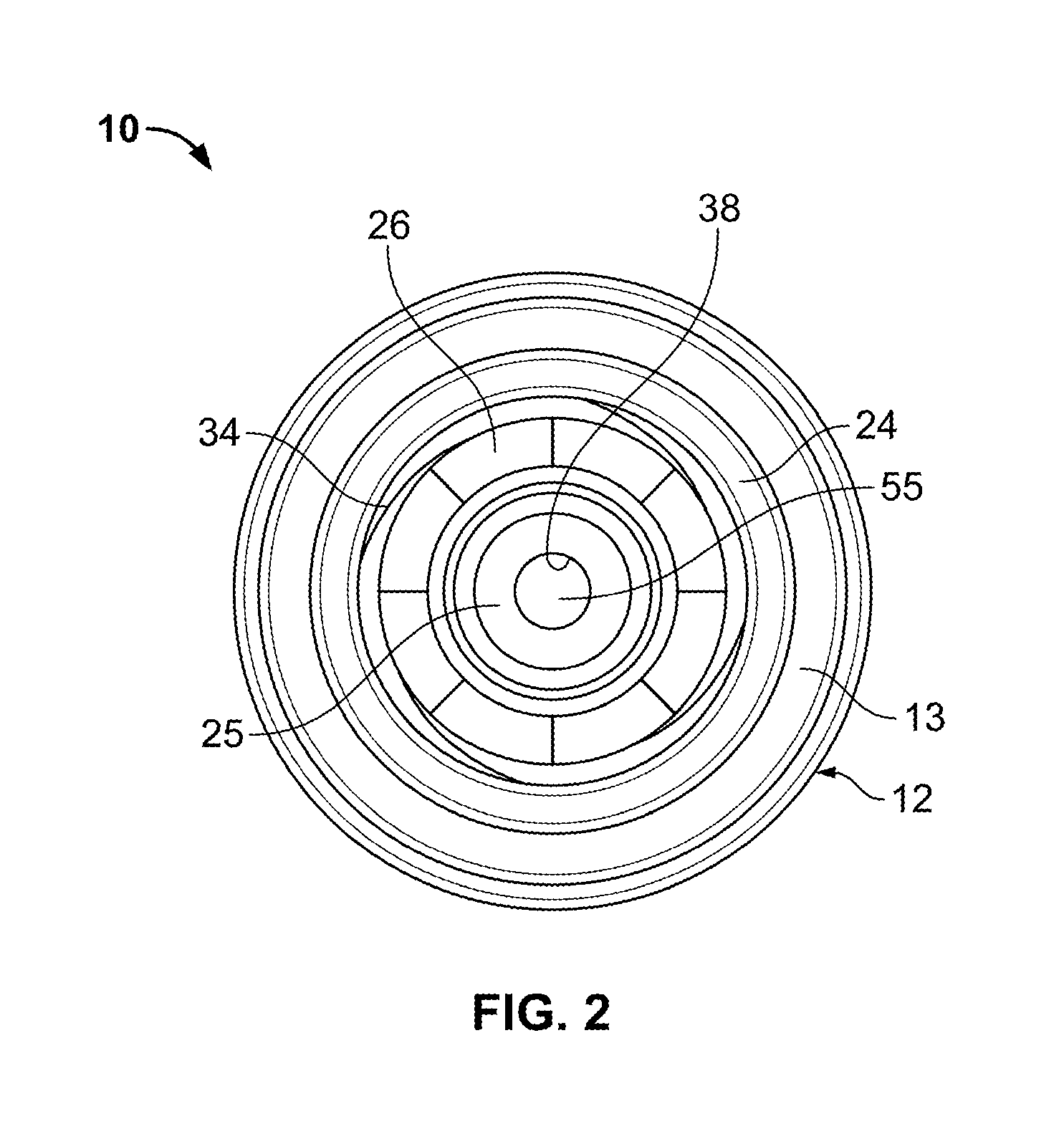
[0075]Certain embodiments as disclosed herein provide for a valve apparatus and method for controlling fluid flow through fluid line from a syringe or other fluid supply to a patient or a line connected to a patient. Although embodiments of valves, connecting devices, and assemblies are described herein with respect to medical connections, such valves, connecting devices, and assemblies are not limited to medical connections alone but may be applicable to any connection device or assembly that could benefit from the use of a rotational actuation force, status indicators, and / or any of the other features described herein.

[0076]After reading this description it will become apparent to one skilled in the art how to implement the invention in various alternative embodiments and alternative applications. However, although various embodiments of the present invention will be described herein, it is understood that these embodiments are presented by way of example only, and not limitation....


PUM


Abstract

A valve is provided for controlling flow along a fluid line that includes an outer shell and an inner housing slidably disposed therein that includes connector threads surrounding a boss on one end and a passage through the boss. A backing member is coupled to the outer shell and has a sealing pin extending into the passage. A connector may be threaded into the one end of the inner housing, thereby slidably engaging the connector threads, causing the inner housing to move helically from a closed position wherein the sealing pin engages an outlet opening at the distal end of the boss to seal the outlet opening and an open position wherein the inner housing is directed away from the sealing pin to open a fluid path through the valve, around the pin, and through the outlet opening.

Description

RELATED APPLICATION[0001]The present invention claims the benefit of U.S. provisional pat. app. No. 61 / 423,204 filed on Dec. 15, 2010 and U.S. provisional pat. app. No. 61 / 511,457 filed on Jul. 25, 2011, the contents of which are incorporated herein by reference in their entirety.FIELD OF THE INVENTION[0002]The present invention relates generally to apparatus and methods for controlling flow. More particularly, the present invention relates to devices, assemblies, and / or methods for controlling fluid flow, e.g., to connectors and / or valves for controlling flow through an IV or other fluid line into a patient, a syringe, container, and / or other medical device, and / or to systems including such connectors and / or valves.BACKGROUND OF THE INVENTION[0003]Controlling flow is an important and useful tool in virtually all scientific fields. One such field where controlling flow is highly useful is in the medical arena. For example, it may be useful to control flow during infusion, e.g., when...

Claims


Application Information

Patent Timeline
Patent Type & Authority Patents(United States)
IPC IPC(8): A61M5/00
CPCA61M39/26A61M2039/267A61M39/10A61M2039/2486
Inventor STROUP, DAVID KARL
Owner INFUSION INNOVATIONS
Why Eureka
Try Eureka