

Illumination controller and illumination driving system
a technology of illumination controller and driving system, which is applied in the direction of electric variable regulation, process and machine control, instruments, etc., can solve the problems increasing the complexity of assembling circuit and the cost of circuit, and achieving the effect of increasing the complexity of assembling circuit and the cost of circuit, and relatively low cost of circui
- Summary
- Abstract
- Description
- Claims
- Application Information
AI Technical Summary
Benefits of technology
Problems solved by technology
Method used
Image

Examples
first embodiment
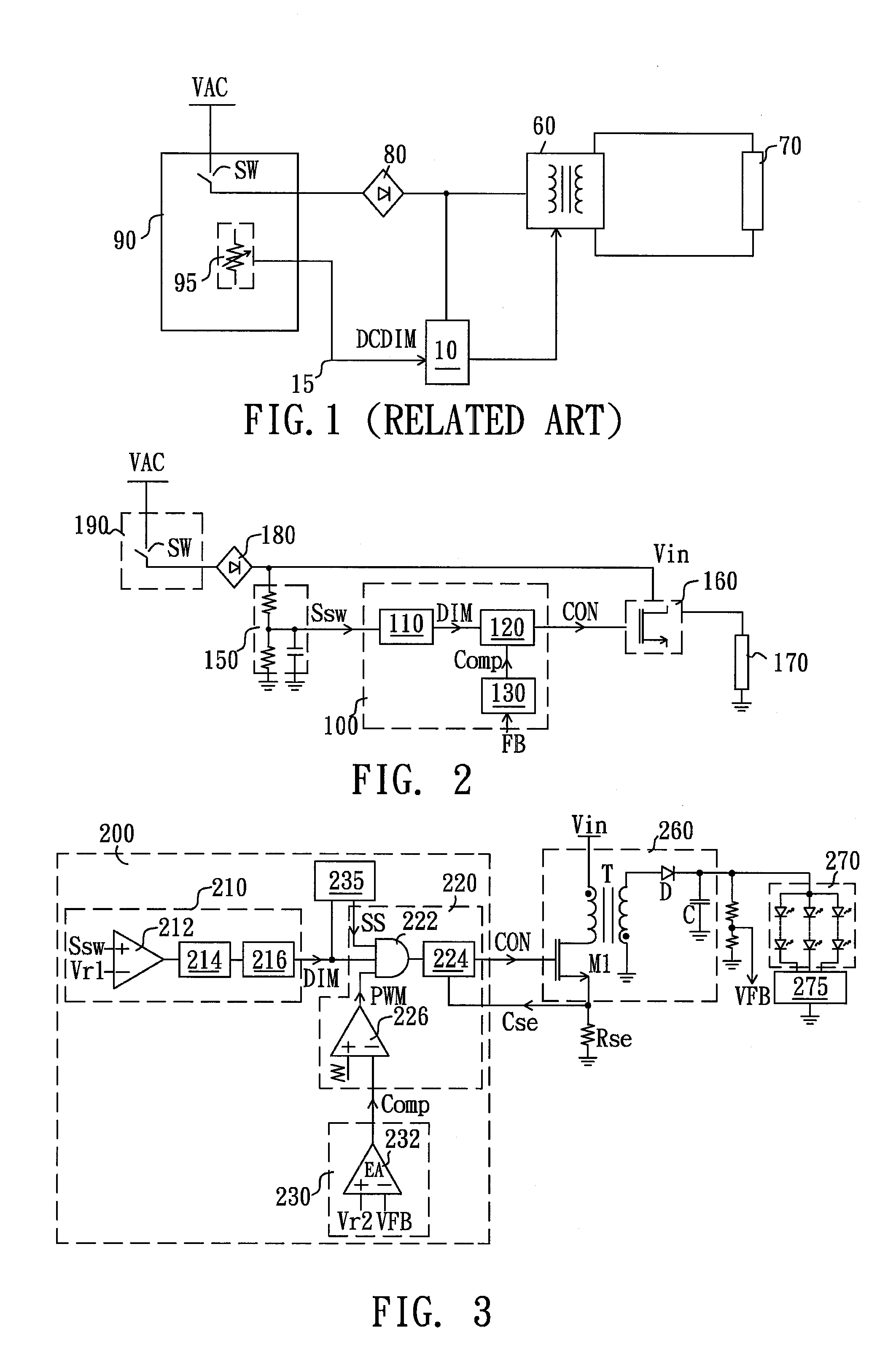
[0022]FIG. 3 is a schematic circuit of an illumination driving system according to the invention. Referring to FIG. 3, the illumination driving system includes an illumination controller 200 and a converting circuit 260. The converting circuit 260 receives a DC input power source Vin and converts the DC input power source Vin into an output voltage so as to drive a light source 270. In the present embodiment, the converting circuit 260 is a flyback converting circuit including a switch SW, a transformer T, a rectifying diode D, and an output capacitor C. The light source 270 is a light emitting diode (LED) module including a plurality of LED strings coupled in parallel, and the light source 270 is coupled to the converting circuit 260 to receive the electric power required for light emitting. In order to uniform the brightness of each LEDs in the light source 270, the light source 270 may be coupled with a current balancing element 275 to uniform the currents flowing through the LED...
second embodiment
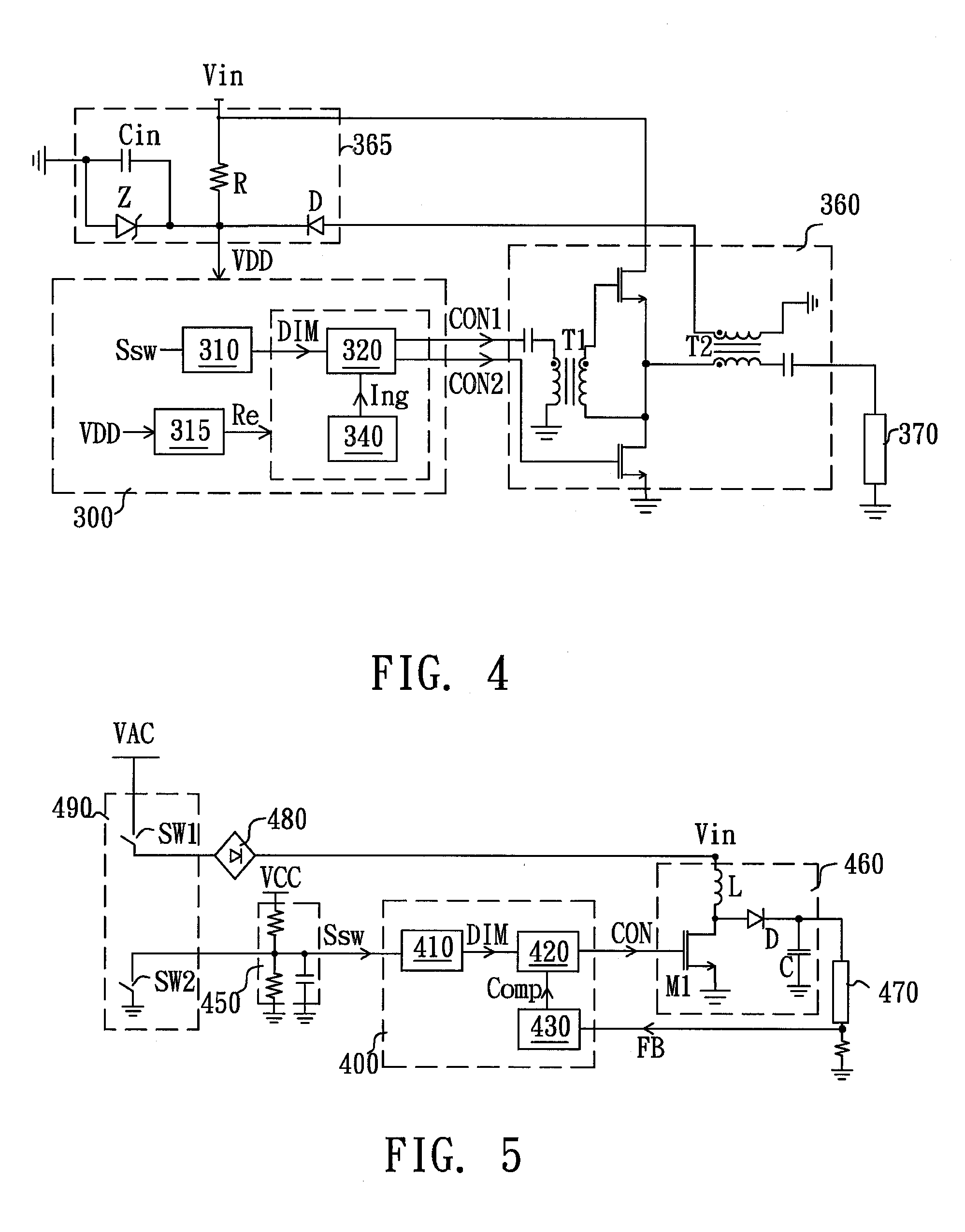
[0025]FIG. 4 is a schematic circuit of an illumination driving system according to the invention. Referring to FIG. 4, the illumination driving system includes an illumination controller 300 and a converting circuit 360. The converting circuit 360 receives a DC input power source Vin and converts the DC input power source Vin into an output voltage so as to drive a light source 370. In the present embodiment, the light source 370 is a discharging lamp module, such as a cold cathode fluorescent lamp (CCFL) module, a hot cathode fluorescent lamp (HCFL) module, and so on. The converting circuit 360 mainly includes a driving transformer T1, a transformer T2, and two switches coupled in series between the DC input power source DC and ground. The illumination controller 300 generates two control signals CON1 and CON2 to respectively control the states of the two switches, so as to control the value of the electric power provided to the light source 370 by the converting circuit 360. The i...
third embodiment
[0028]FIG. 5 is a schematic circuit of an illumination driving system according to the invention. Referring to FIG. 5, the illumination driving system includes an illumination controller 400 and a converting circuit 460. The converting circuit 460 receives a DC input power source Vin and converts the DC input power source Vin into an output voltage so as to drive a light source 470. In the present embodiment, the light source 470 is a light emitting diode (LED) module and the converting circuit 460 is a DC / DC boost converter. The converting circuit 460 mainly includes an inductor L, a rectifying diode D, an output capacitor C and a switch SW. The illumination controller 400 generates a control signal CON to control the states of the switch SW, so as to control the value of the electric power provided to the light source 470 by the converting circuit 460. The illumination controller 400 includes a dimming unit 410 and a control unit, wherein the control unit includes a duty cycle con...
PUM
 Abstract
Description
Claims
Application Information