Device for holding wafer shaped articles

a technology of wafers and chucks, which is applied in the direction of electrical appliances, semiconductor/solid-state device manufacturing, and applications. it can solve the problems affecting the desired controlled wafer shift, and excessive wear and groove formation of the pins, so as to reduce achieve the desired control of the wafer shift. , the effect of reducing the working lifetime of the chuck

Active Publication Date: 2011-11-10
LAM RES AG
View PDF9 Cites 7 Cited by
  • Summary
  • Abstract
  • Description
  • Claims
  • Application Information

AI Technical Summary

Benefits of technology

[0008]The present inventors have discovered that, in chucks of the type described above, the pins close very rapidly, which causes excessive wear and groove formation in the pins over time. This can result in decreasing the working lifetime of the chuck, and impairing the desired controlled wafer shift during wafer processing.

Problems solved by technology

The present inventors have discovered that, in chucks of the type described above, the pins close very rapidly, which causes excessive wear and groove formation in the pins over time.
This can result in decreasing the working lifetime of the chuck, and impairing the desired controlled wafer shift during wafer processing.

Method used


Image

  • Device for holding wafer shaped articles
  • Device for holding wafer shaped articles
  • Device for holding wafer shaped articles

Examples


Embodiment Construction

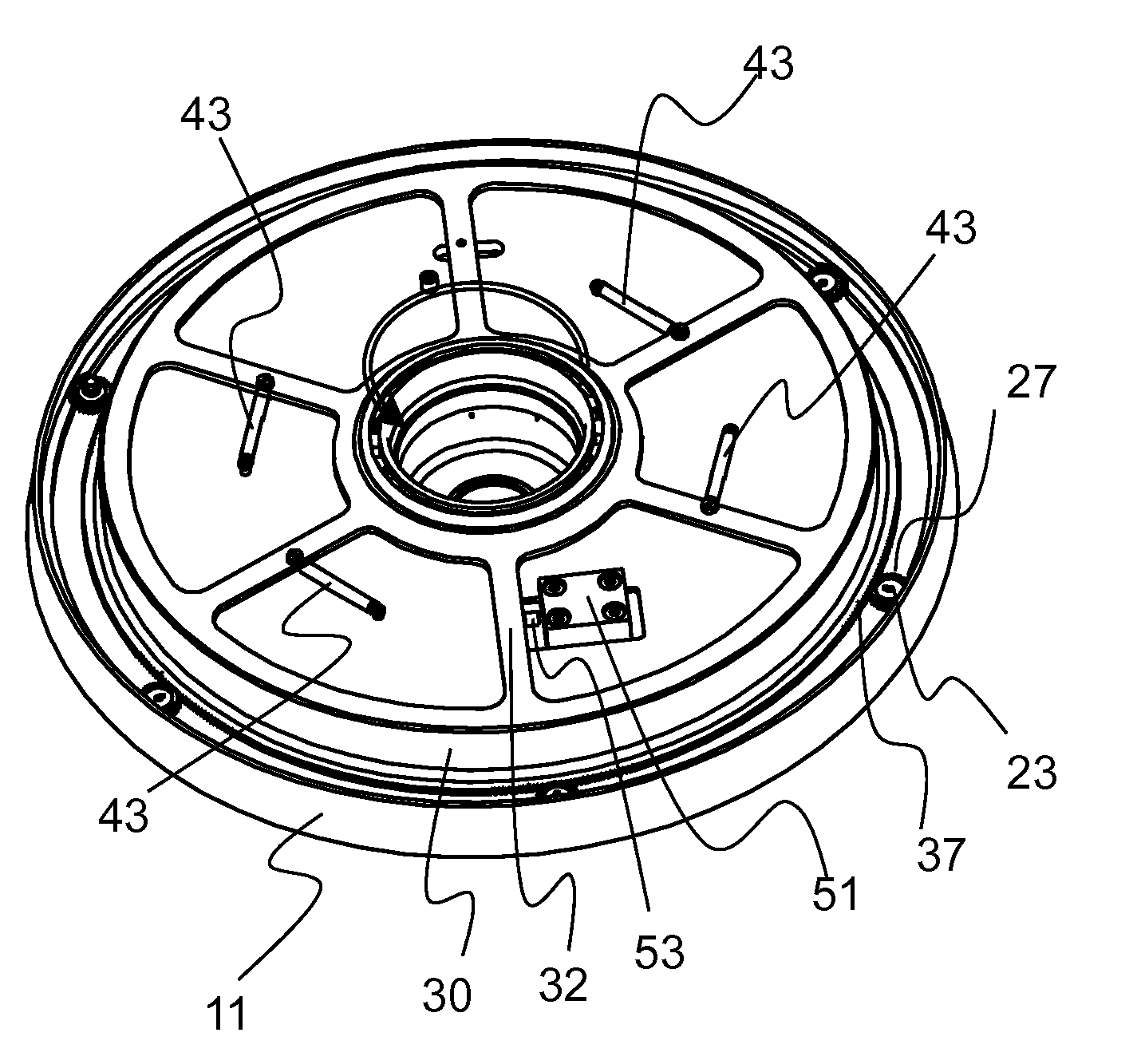
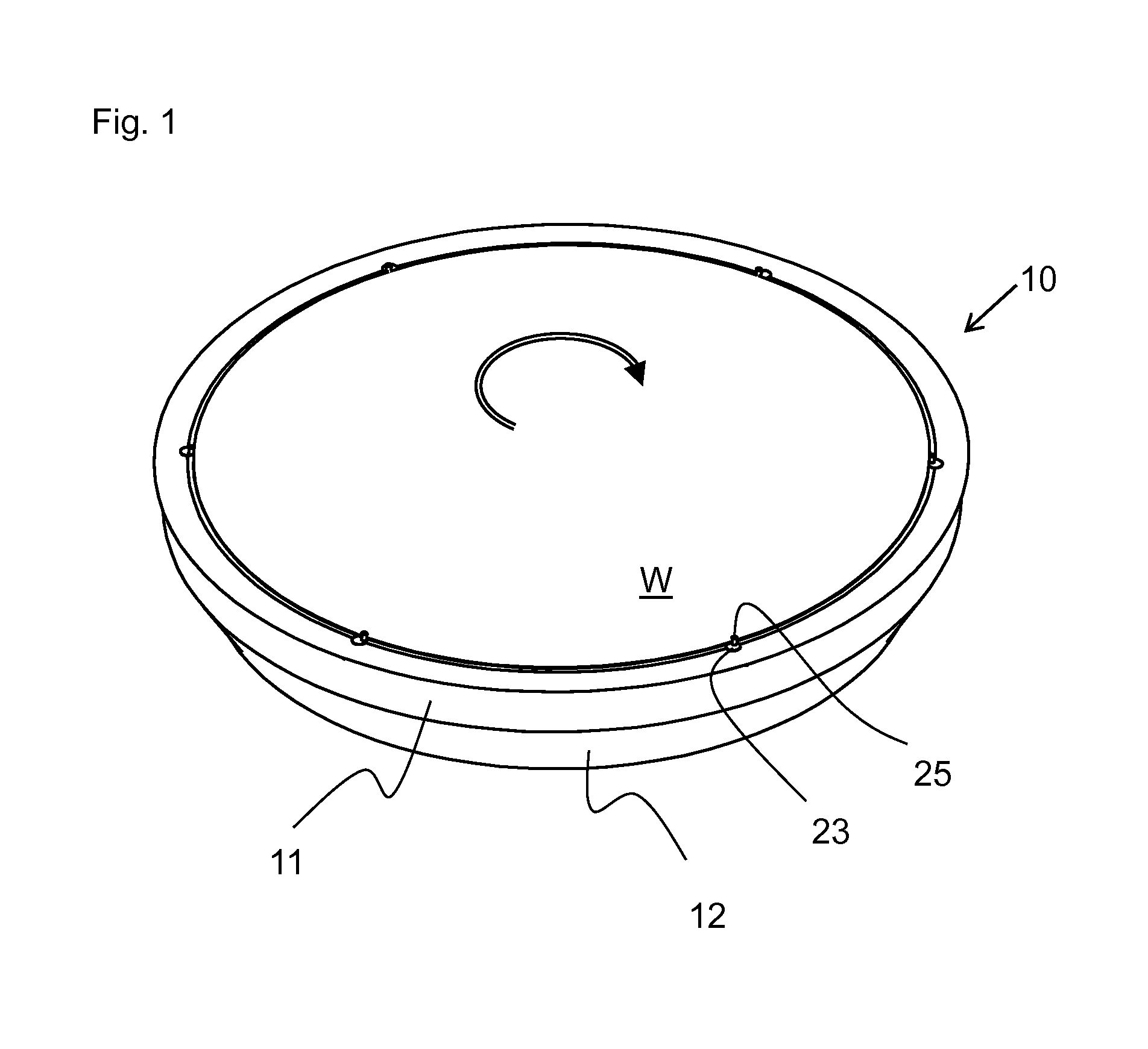
[0018]In FIG. 1, a chuck 10 is in a working position, which means that a wafer W is held by the pins 25. The circular arrow depicts the clockwise rotation of the chuck. Chuck 10 includes an upper base body 11 and a lower base body 12. The wafer is held peripherally by a series of pin assemblies 23, each including an eccentrically mounted chuck pin 25. As discussed above, when the pin assembly 23 is rotated about its axis (parallel to the rotation axis of the chuck) the pin 25 is moved towards and away from the wafer edge.

[0019]Chuck 10 is preferably a Bernoulli chuck, where the wafer floats on a gas cushion provided by a number of gas nozzles (not shown) and is also supported from below by the gas cushion due to the Bernoulli effect.

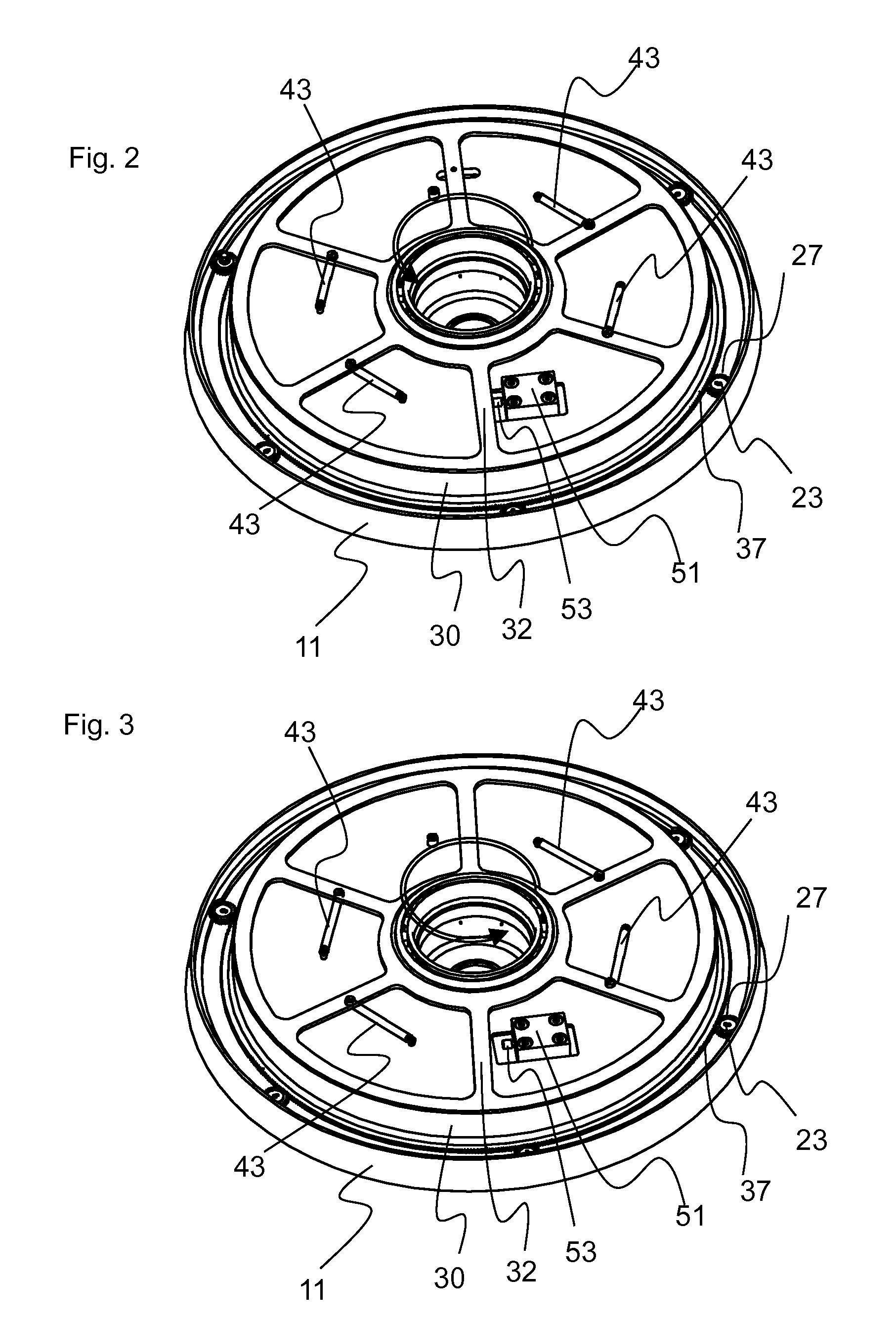
[0020]In FIG. 2 the circular arrow again depicts the clockwise rotation of the chuck, although the arrow itself is directed counterclockwise due to the chuck being shown from below in this figure. For ease of illustration the lower base body 12 is not sh...


PUM


Abstract

A spin chuck for holding semiconductor wafers includes one or more damping mechanisms to limit the force with which chuck pins impact the wafer edge following wafer shift. The damping mechanism may be a linear or rotary dashpot. The dashpot or dashpots are mounted on a surface of the chuck body and include a control arm that contacts a common gear ring that in turn drives the chuck pins during radially inward and outward movement.

Description

BACKGROUND OF THE INVENTION[0001]The invention relates to devices for holding wafer-shaped articles, such as semiconductor wafers.[0002]Semiconductor wafers are subjected to various surface treatment processes such as etching, cleaning, polishing and material deposition. To accommodate such processes, a single wafer may be supported in relation to one or more treatment fluid nozzles by a chuck associated with a rotatable carrier, as is described for example in U.S. Pat. Nos. 4,903,717 and 5,513,668.[0003]The patents referenced above operate on the Bernoulli principle, such that the wafer receives subjacent support from a gas cushion rather than by contact with the chuck. Such chucks nevertheless ordinarily include a circular series of pins that are positioned radially outwardly of a wafer positioned on the chuck. Those pins prevent lateral displacement of the wafer relative to the chuck.[0004]As described in U.S. Pat. No. 4,903,717, it is also advantageous to construct the pins such...

Claims


Application Information

Patent Timeline
Patent Type & Authority Applications(United States)
IPC IPC(8): H01L21/687
CPCH01L21/68785H01L21/68728H01L21/68792
Inventor FRANK, DIETERPUGGL, MICHAELFUCHS, ROMANLACH, OTTO
Owner LAM RES AG
Why Eureka
Try Eureka