Endoscope apparatus and bending drive control method

Active Publication Date: 2011-11-10
OLYMPUS CORP
View PDF7 Cites 17 Cited by
  • Summary
  • Abstract
  • Description
  • Claims
  • Application Information

AI Technical Summary

Benefits of technology

[0014]a bending control section that drives bending of the bending drive section along the plane.
[0015]A bending drive control method according to the present invention includes:

Problems solved by technology

For example, a transverse colon in a large intestine sags and causes difficulty in insertion of an insertion portion to a hepatic flexure side on a deep part side as it is.

Method used


Image

  • Endoscope apparatus and bending drive control method
  • Endoscope apparatus and bending drive control method
  • Endoscope apparatus and bending drive control method

Examples


first embodiment

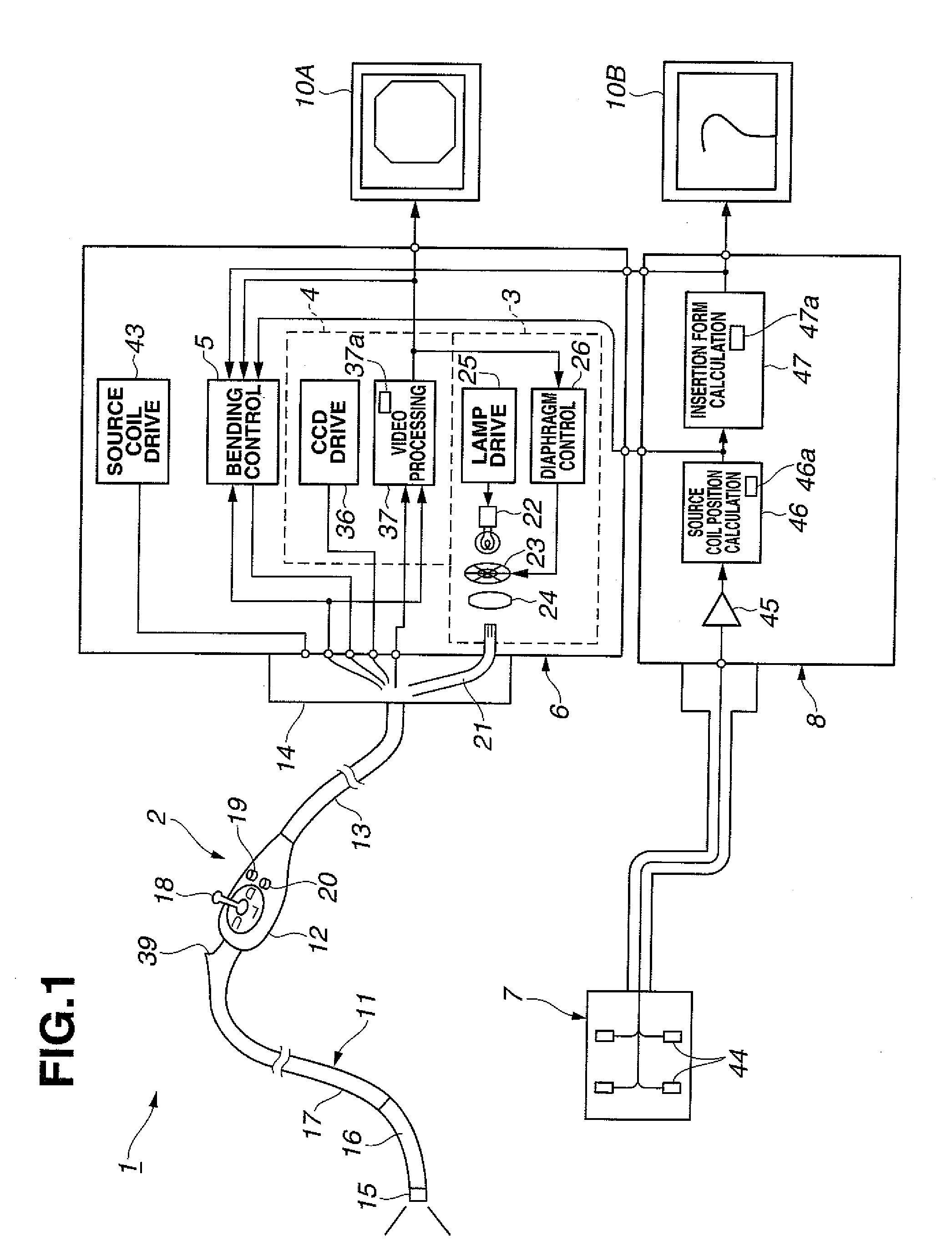
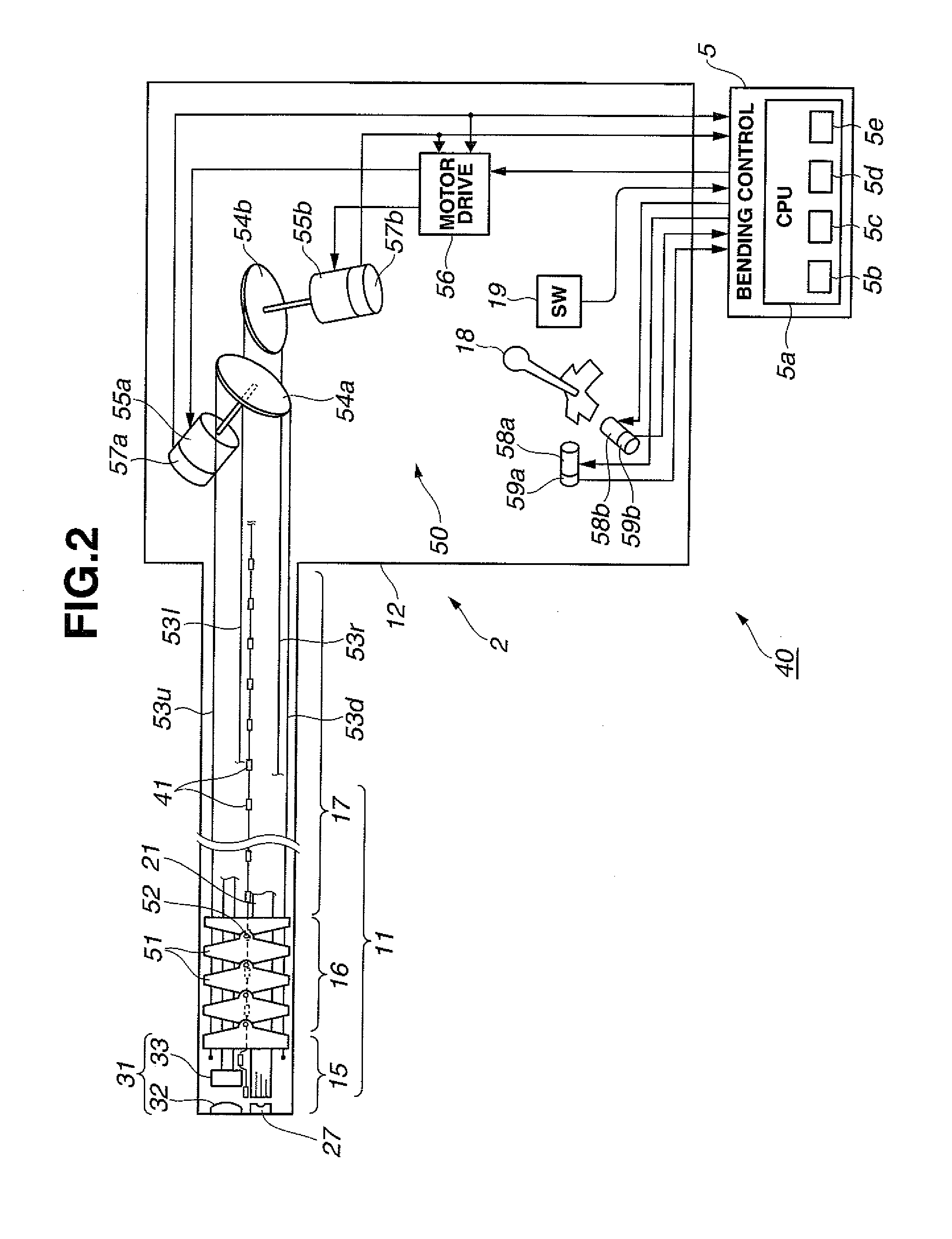
[0039]As illustrated in FIG. 1, an endoscope apparatus 1 according to a first embodiment of the present invention includes an endoscope 2 to be inserted into, e.g., a body cavity, a light source section 3 that supplies illuminating light to the endoscope 2, a signal processing section 4 that performs signal processing for image pickup means included in the endoscope 2, and a video processor 6 including, e.g., a bending control section 5 that performs control of bending of an bending portion of the endoscope 2, therein.

[0040]The endoscope apparatus 1 further includes: a sensing coil unit 7 that detects positions of source coils for position detection provided in the endoscope 2; an insertion shape detection apparatus 8 that detects an insertion shape of an insertion portion 11 of the endoscope 2 by means of a detection signal from the sensing coil unit 7 and creates an image thereof; and monitors 10A and 10B that display an endoscope image picked up by the image pickup means and an i...

second embodiment

[0137]Next, a second embodiment of the present invention will be described. In the first embodiment, the insertion portion 11 of the endoscope 2 is provided with one bending portion 16 at the rear end of the distal end portion 15.

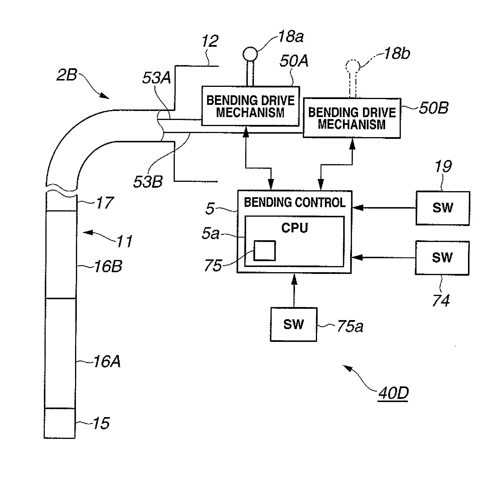
[0138]Meanwhile, an endoscope 2B according to the present embodiment is a two step-bending endoscope whose insertion portion 11 is provided with a first bending portion 16A, which corresponds to the bending portion 16 in the first embodiment, and a second bending portion 16B at a rear end of the first bending portion 16A.

[0139]FIG. 9 illustrates a configuration of a part around a bending control apparatus 40B according to the second embodiment.

[0140]The first bending portion 16A and the second bending portion 16B are connected to a first bending drive mechanism 50A and a second bending drive mechanism 50B via angle wires 53A (53A represents 53u, 53d, 53l and 53r in FIG. 2) and 53B (53B also has a configuration similar to that of 53A) for driving bending of ...

third embodiment

[0164]Next, the third embodiment of the present invention will be described. FIG. 13 illustrates a configuration of a bending control apparatus 40C according to the present embodiment. The bending control apparatus 40C is further provided with a bending start switch 74 in the bending control apparatus 40B illustrated in FIG. 9 in the second embodiment. The setting section 71 and the setting switch 71a have been removed.

[0165]In the second embodiment, the bending control section 5 performs control so as to drive bending of the second bending portion 16B with the first bending portion 16A kept at the bending limit 72 when the first bending portion 16A falls beyond the bending limit 72.

[0166]In the present embodiment, only during the period in which the bending start switch 74 is on, a bending control section 5 performs control to drive bending of a second bending portion 16B in a first bending drive direction for a first bending portion 16A.

[0167]Instead of the bending start switch 74...


PUM


Abstract

An endoscope apparatus includes: an insertion portion including a bending portion provided on a distal end side thereof; a bending drive section that drives bending of the bending portion; an insertion shape detection section that detects an insertion shape of the distal end side of the insertion portion as insertion shape information; a curved state detection section that detects a curved state based on the insertion shape information as curve information; a plane calculation section that performs a calculation to estimate a plane for driving bending of the bending portion from the detected curve information; and a bending control section that drives bending of the bending drive section along the estimated plane.

Description

CROSS REFERENCE TO RELATED APPLICATION[0001]This application is a continuation application of PCT / JP2010 / 061590 filed on Jul. 8, 2010 and claims benefit of Japanese Application No. 2009-228025 filed in Japan on Sep. 30, 2009, the entire contents of which are incorporated herein by this reference.BACKGROUND OF THE INVENTION[0002]1. Field of the Invention[0003]The present invention relates to an endoscope apparatus that electrically drives bending of a bending portion of an endoscope, and a bending drive control method.[0004]2. Description of the Related Art[0005]Endoscopes with image pickup means and a bendable bending portion on a distal end side of an insertion portion are widely used for inspection, examination or the like of an inside of a body cavity.[0006]Also, smooth insertion of an insertion portion into an intricately-curved body cavity such as a large intestine may require skills. For example, a transverse colon in a large intestine sags and causes difficulty in insertion o...

Claims


Application Information

Patent Timeline
Patent Type & Authority Applications(United States)
IPC IPC(8): A61B1/005
CPCA61B1/00006A61B1/0016A61B1/0052A61B1/05A61B5/062A61B5/064A61B5/065A61B1/31A61B1/00042A61B1/009
Inventor TANAKA, HIDEKI
Owner OLYMPUS CORP
Why Eureka
Try Eureka