
Projector and control method

Active Publication Date: 2011-11-17
SEIKO EPSON CORP
View PDF7 Cites 3 Cited by
  • Summary
  • Abstract
  • Description
  • Claims
  • Application Information

AI Technical Summary

Benefits of technology

[0006]An advantage of some aspects of the invention is to provide a projector and a control method which can perform control according to an instruction given to an individual image by solving the problem described above.

Problems solved by technology

However, with the above-described method, it is impossible to perform such display.

Method used


Image

  • Projector and control method
  • Projector and control method
  • Projector and control method

Examples


first embodiment

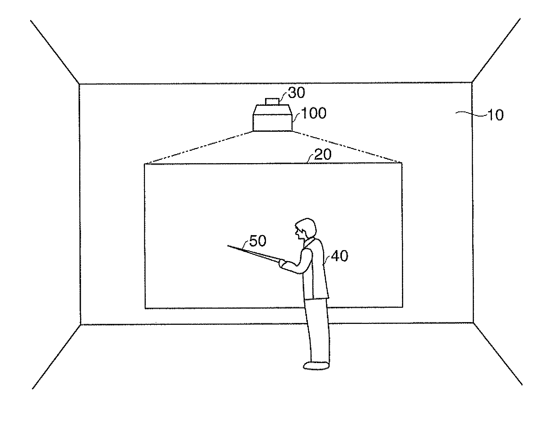
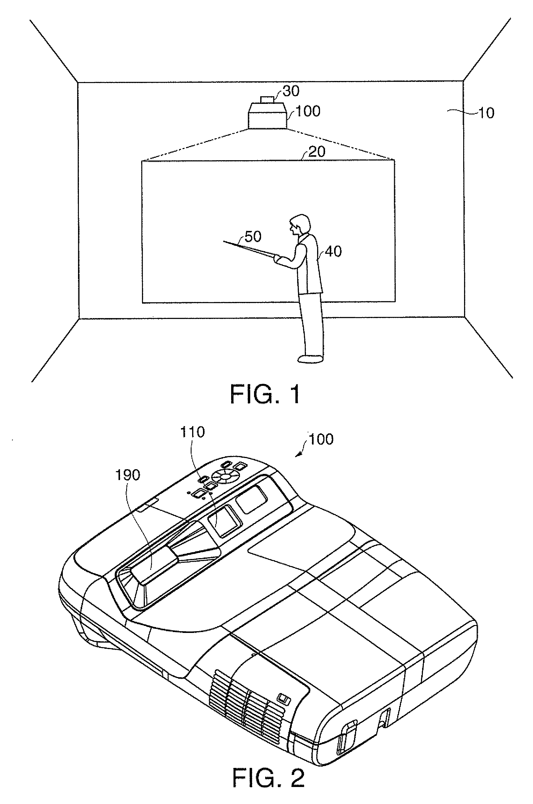
[0030]FIG. 1 is a diagram showing an example of a projection status in a first embodiment. For example, in a conference room, a presenter 40 is making a presentation by using an instruction stick 50 which is a type of instruction tool having a light-emitting function. In an upper part of a wall 10 in the conference room, a single focus projector 100 is attached by fittings 30. The projector 100 which is a type of display device is projecting an image 20 onto the wall 10 which is a type of projection target region.

[0031]FIG. 2 is an appearance diagram of the projector 100 in the first embodiment. The projector 100 of FIG. 2 shows a state in which the projector 100 installed in FIG. 1 is turned upside down (a state in which the bottom face of the projector 100 becomes the top face thereof). In an inclined face which faces the wall 10, the inclined face in the bottom face of the projector 100, a projecting section 190 and an image-taking section 110 are provided. This allows the projec...


PUM


Abstract

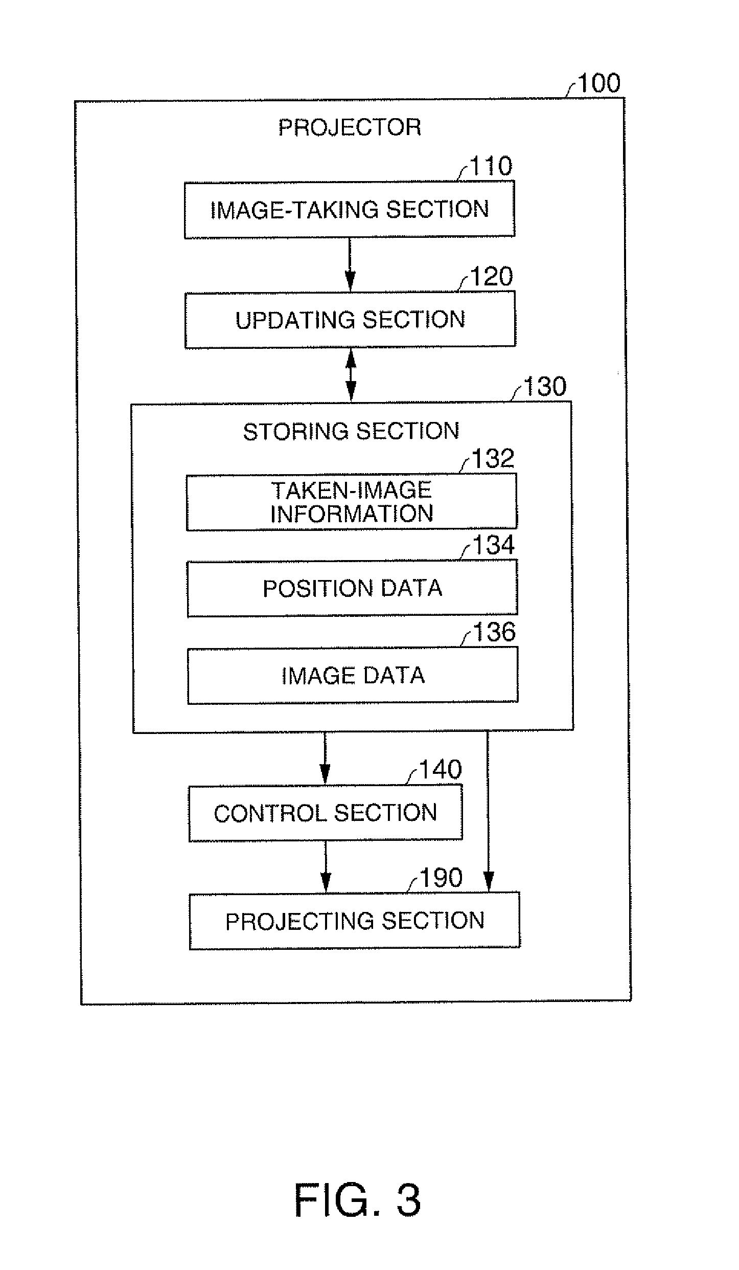
A projector includes: an image-taking section; an updating section; a storing section storing taken-image information, position data and image data; a projecting section projecting a whole image including an individual image and having a function of adjusting the size of the whole image; and a control section performing control so as to make the projecting section adjust the size of the whole image according to the movement of the individual image in a state in which the whole image includes the whole of the individual image.

Description

BACKGROUND[0001]1. Technical Field[0002]The present invention relates to projectors and control methods.[0003]2. Related Art[0004]For example, JP-A-2007-219217 describes a method for inputting instruction information showing an enhancing instruction to enhance part of an image, enhancing the part according to an instruction content based on the instruction information, and projecting a zoom image which is an image obtained by enlarging a region including the above part.[0005]However, the above-described method is a method for enlarging part of an image, and the size of the whole image does not change. For example, when the user additionally displays a new individual image in addition to the existing individual image, it is desirable to display the new individual image in an empty space created as a result of the size of the whole image having been enlarged. However, with the above-described method, it is impossible to perform such display.SUMMARY[0006]An advantage of some aspects of...

Claims


Application Information

Patent Timeline
IPC IPC(8): G09G5/00
CPCG06F3/0425G09G3/002H04N9/3194G09G2340/04H04N9/3179G09G5/14
Inventor KIKUCHI, YOSUKE
Owner SEIKO EPSON CORP
Learn More