Digital camera system and method for maximizing television viewing area

Inactive Publication Date: 2005-06-09
HEWLETT PACKARD DEV CO LP
View PDF10 Cites 2 Cited by
  • Summary
  • Abstract
  • Description
  • Claims
  • Application Information

AI Technical Summary

Benefits of technology

[0006] The present invention provides for a digital camera system and method that automatically maximizes television viewing area when a television is used to view images stored in or transferred from a digital camera. In an embodiment of the present invention, a test signal or image comprising a beacon is output from the digital camera and is displayed on a television screen. A user points the camera at the television.
[0007] Firmware that runs on the digital ca

Problems solved by technology

This causes clipping to occur a

Method used


Image

  • Digital camera system and method for maximizing television viewing area
  • Digital camera system and method for maximizing television viewing area
  • Digital camera system and method for maximizing television viewing area

Examples


Embodiment Construction

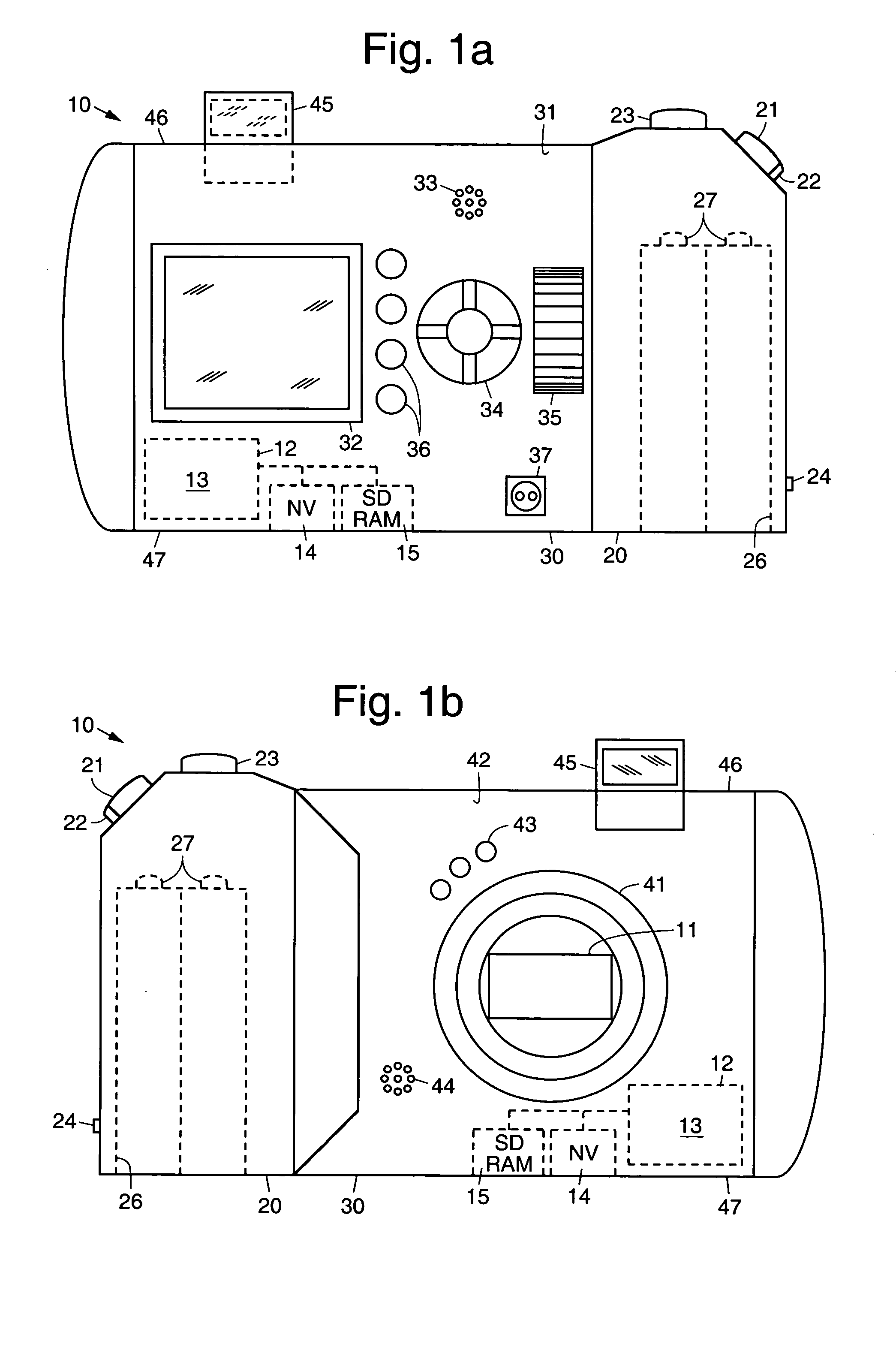
[0012] Referring to the drawing figures, FIGS. 1a and 1b are rear and front views, respectively, of an exemplary digital camera 10 implemented in accordance with the principles of the present invention. As is shown in FIGS. 1a and 1b, the exemplary digital camera 10 comprises a handgrip section 20 and a body section 30. The handgrip section 20 includes a power button 21 or switch 21 having a lock latch 22, a record button 23, a strap connection 24, and a battery compartment 26 for housing batteries 27. The batteries may be inserted into the battery compartment 26 through an opening adjacent a bottom surface 47 of the digital camera 10.

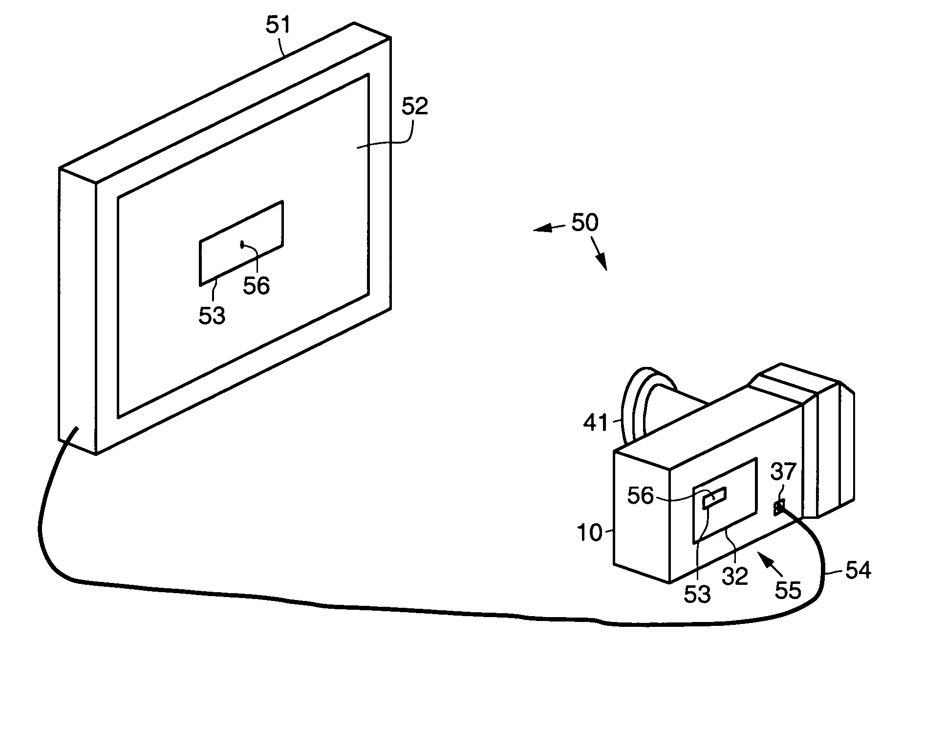
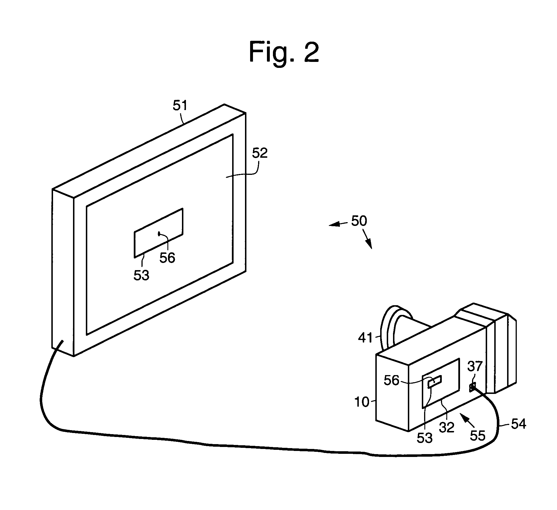
[0013] As is shown in FIG. 1a, a rear surface 31 of the body section 30 comprises a liquid crystal display (LCD) 32 or viewfinder 32, a rear microphone 33, a joystick pad 34, a zoom control dial 35, a plurality of buttons 36 for setting functions of the camera 10 and a video output port 37 for downloading images to a computer, for example. As is shown...


PUM


Abstract

A digital camera system and method that automatically maximizes television viewing area when a television is used to view images stored in or transferred from a digital camera. A test signal or image comprising a beacon is output from the digital camera and is displayed on a television screen. A user points the camera at the television. Firmware that runs on the digital camera moves the test signal and beacon horizontally and vertically towards respective edges of the television screen until the beacon is lost at each edge, and determines or calculates how much viewing area is available on the television screen. The autocalibration firmware then automatically adjusts the size of images sent from the digital camera to the television to maximize the viewing area on the television while minimizing cropping or clipping of the images.

Description

TECHNICAL FIELD [0001] The present invention relates generally to digital cameras and methods. BACKGROUND [0002] Digital cameras certainly have come of age when it comes to capturing and instantly reviewing photographs. More and more however, digital cameras are often used as a sharing device for showing pictures stored in the camera with friends and family. Many times this is done using a video output port of the camera and a conventional television. [0003] The television signal is generally much larger than that displayed on the television. There are large borders across the top, bottom, left and right of the television that are not displayed. The television signal is on the order of 1700 pixels wide, while only 600 pixels are displayed. Due to calibration issues, the 600 pixels can vary such that the television displays 700 or 500 pixels, for example. Thus, the number of pixels that are displayed varies. The same thing occurs with the top and bottom borders of the television. [00...

Claims


Application Information

Patent Timeline
IPC IPC(8): H04N1/00H04N5/232H04N5/262H04N17/00
CPCH04N1/00291H04N5/232H04N2201/0084H04N2101/00H04N5/2628H04N23/60
Inventor VOSS, JAMES S.OWENS, JAMES W.
Owner HEWLETT PACKARD DEV CO LP
Why Eureka
Try Eureka