Skylight for data center machine room

A technology for data centers and computer rooms, applied in the field of skylights, which can solve problems such as the inability to open and close a single skylight, small viewing area of ​​glass, troublesome installation and disassembly, etc., to achieve the effect of maximizing the viewing area, small overall weight, and simple structure

Pending Publication Date: 2020-06-05
南京迪港科技有限责任公司
View PDF0 Cites 2 Cited by
  • Summary
  • Abstract
  • Description
  • Claims
  • Application Information

AI Technical Summary

Problems solved by technology

Traditional skylights are bulky, which makes installation and disassembly troublesome. The viewing area of ​​the glass is small, and it is opened and closed as a whole during use. It cannot be opened and closed for a single skylight, so we need a new type of data center computer room. Skylights to solve the above problems and meet people's needs

Method used


Image

  • Skylight for data center machine room
  • Skylight for data center machine room
  • Skylight for data center machine room

Examples


Embodiment 1

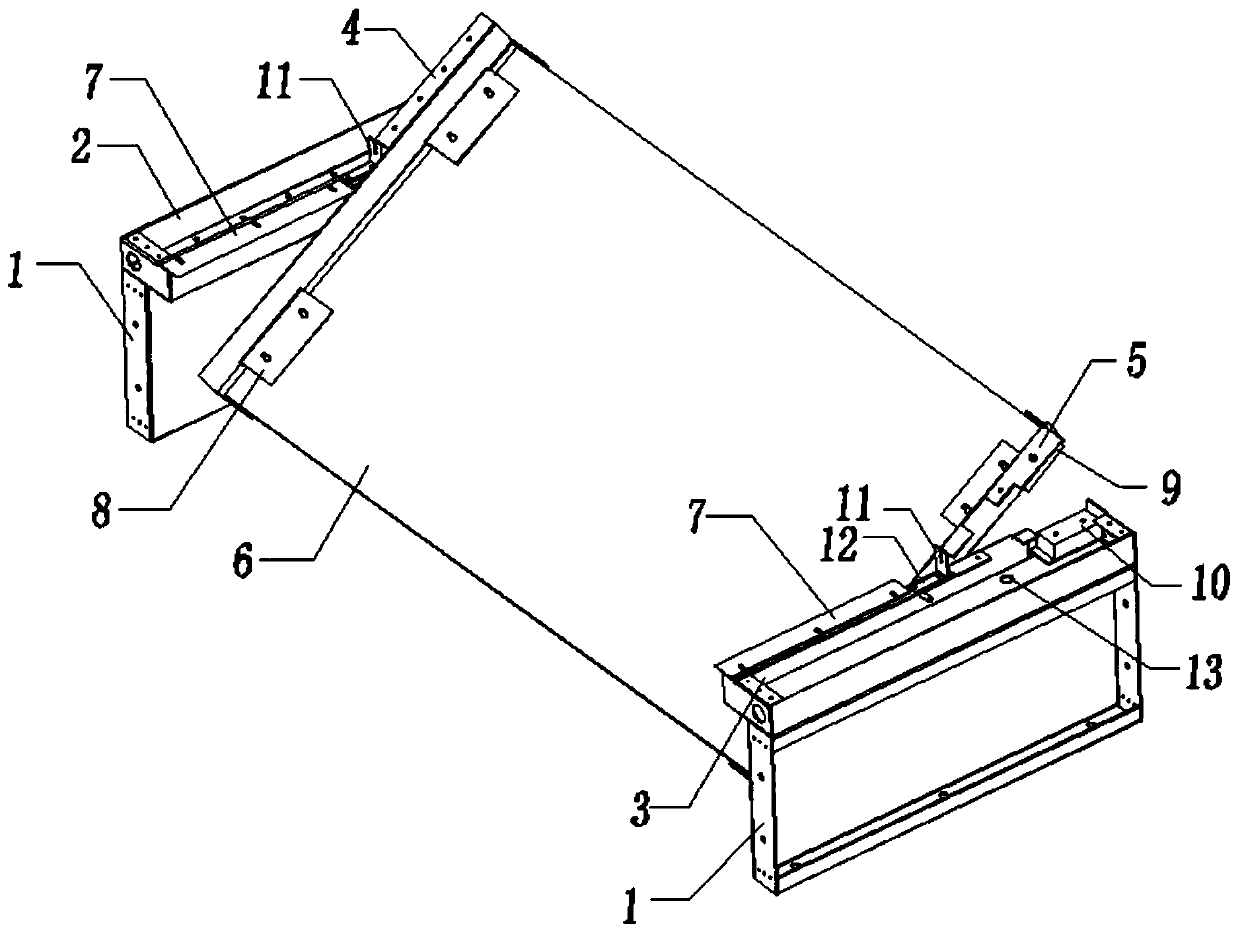
[0028] The present invention provides such Figure 1-10 The shown skylight for a data center computer room includes a cabinet front panel 1 fixed on the top of the cabinet, and the upper surfaces of the two cabinet front panels 1 are equipped with load-bearing mechanisms, and mounting holes 57 are symmetrically arranged in the middle of the inner side of the load-bearing mechanism. One end of the carrying mechanism and the glass bracket is provided with a corresponding locking device, the locking device controls the opening / closing of the glass bracket, the glass bracket is connected with the mounting hole 57 through the connecting column to realize the rotation of the glass bracket, and a The glass plate 6, the supporting mechanism is provided with a rotation limiting device in the direction of rotation of the glass plate 6, the rotation limiting device is composed of an angle limiting part 11 and a baffle plate 7, and the angle limiting part is arranged on one side of the lim...

Embodiment 2

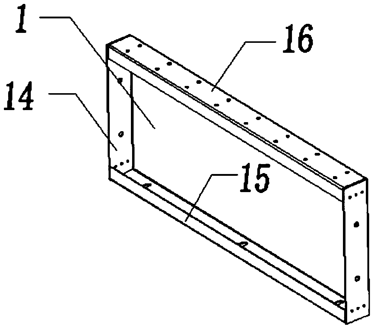
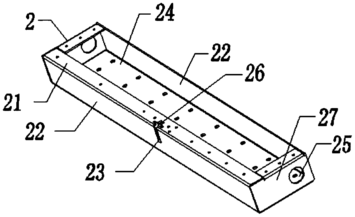
[0030] The present invention provides such Figure 1-10The shown skylight for a data center computer room includes a cabinet front wall 1 fixed on the top of the cabinet, and the cabinet front wall 1 includes a bottom plate 15 screwed to the top of the cabinet, and side plates 14 fixed at right angles to both ends of the bottom plate 15 , and the top plate 16 fixed on the top of the side plate 14 parallel to the bottom plate 15, the bottom plate 15, the side plate 14 and the top plate 16 are integrally welded into the front panel 1 of the cabinet, wherein the surface of the bottom plate 15 has bolt holes for It is screwed to the top of the cabinet, and there are bolt holes on the surface of the top plate 16, and it is screwed to the bolt holes on the surface of the left bracket bottom plate 24 and the right bracket bottom plate 31. The glass plate carrying mechanism includes a glass plate fixing mechanism for fixing the glass plate 6, and a carrying mechanism for fixing the fi...


PUM


Abstract

The invention discloses a skylight for a data center machine room. Bearing mechanisms are installed on the upper surfaces of two machine cabinet front wall plates; installation holes are symmetricallyformed in the middle parts of the inner sides of the bearing mechanisms; corresponding locking devices are arranged at one ends of the bearing mechanisms and glass brackets; the glass brackets are connected with the installation holes through connecting columns so as to realize the rotation of the glass brackets; a glass plate is fixed between the two glass brackets; and rotation limiting devicesare arranged on the bearing mechanisms in the rotation direction of the glass plate. The skylight for the data center machine room is simple in structure, light in overall weight, and more convenientto assemble and disassemble; the left glass bracket, the right glass bracket, a left bracket and a right bracket are positioned on the same horizontal plane, and the upper part of the skylight is thewhole glass plate, so that the visible area is maximized; and when a certain skylight is overhauled, the single skylight can be opened and closed only by carrying out power-off processing on one electromagnetic lock body through a button.

Description

technical field [0001] The invention belongs to the technical field of skylights, and in particular relates to a skylight for a data center machine room. Background technique [0002] There are a large number of cabinets placed in the data center computer room, and a large amount of heat is generated when the cabinets are working. In order to make the cabinet work smoothly, a cold aisle is usually set up in the data center computer room. There is a skylight above the cold aisle. When the skylight is closed, the cold air in the cold aisle can overflow, so that the cold aisle can maintain a good cooling effect. In addition, the skylight also has the function of fire escape. When the cabinet catches fire, open the skylight, and carbon dioxide or other fire extinguishing materials can be sent from the skylight into the cold aisle, so as to realize rapid fire extinguishing. Traditional skylights are bulky, which makes installation and disassembly troublesome. The viewing area ...

Claims


Application Information

Patent Timeline
Patent Type & Authority Applications(China)
IPC IPC(8): E04D13/03E04D13/035
CPCE04D13/03E04D13/0305E04D13/035E04D13/0351
Inventor 李华
Owner 南京迪港科技有限责任公司
Why Eureka
Try Eureka