
Fabric formation for virtual cluster switching

a cluster switching and fabric technology, applied in the field of network design, can solve the problems so as to achieve the effect of reducing the cost of switching

Active Publication Date: 2011-11-24
AVAGO TECH INT SALES PTE LTD
View PDF6 Cites 81 Cited by
  • Summary
  • Abstract
  • Description
  • Claims
  • Application Information

AI Technical Summary

Benefits of technology

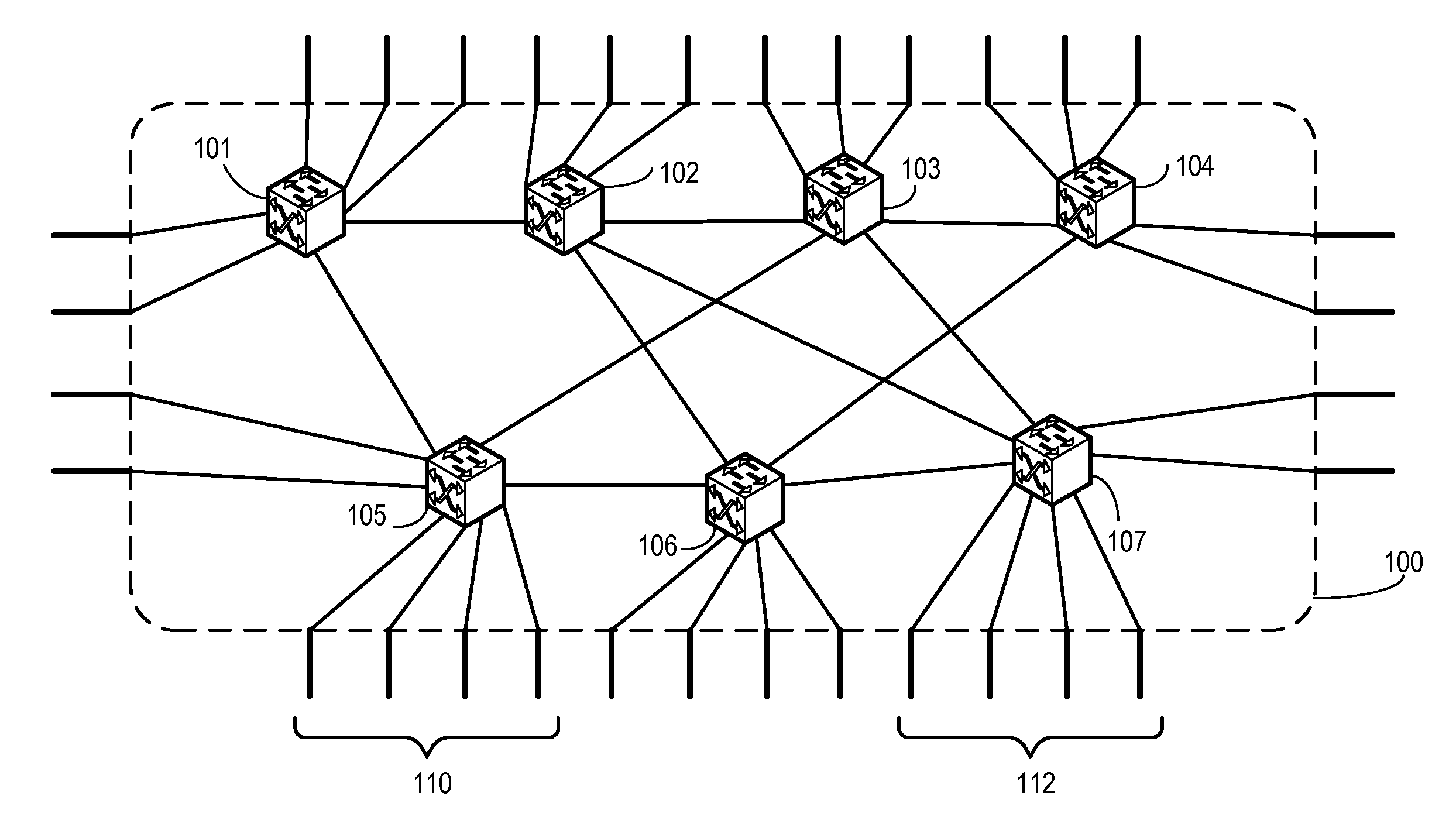
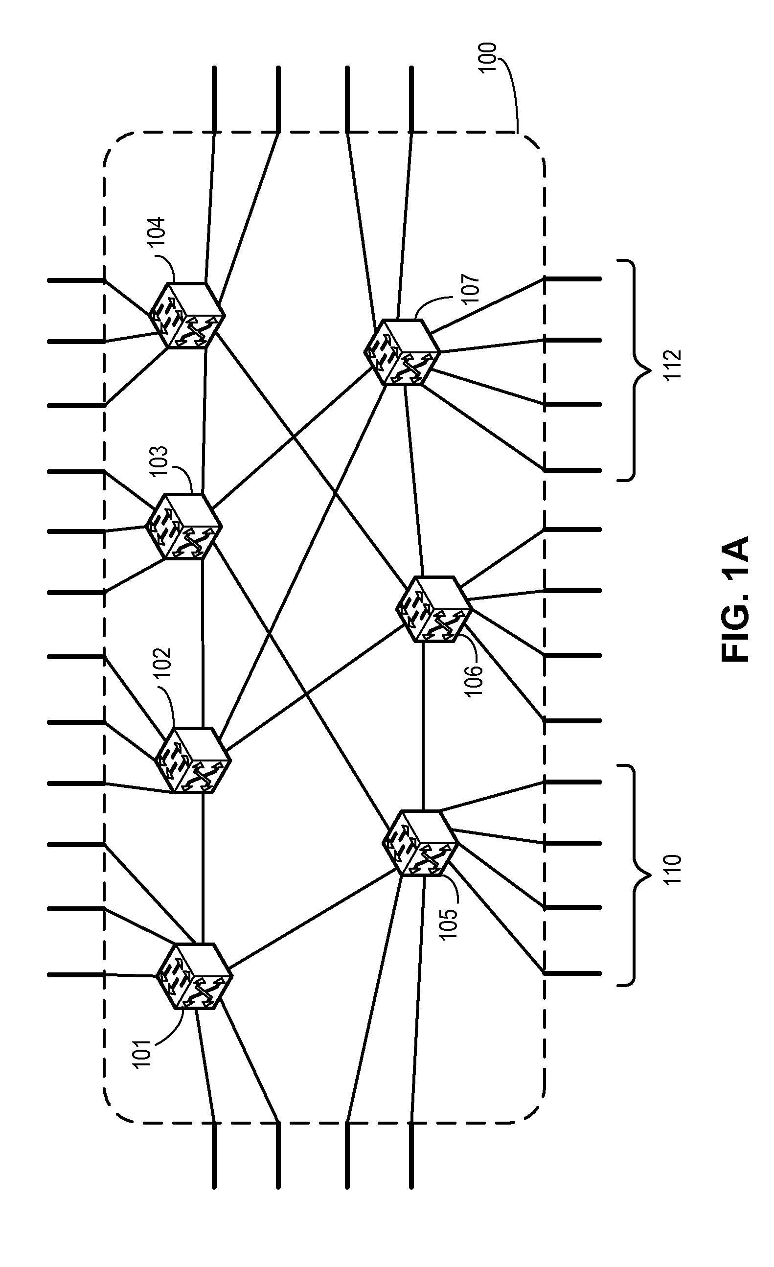
This patent describes a switch system that can connect with another switch through its ports. When the first switch gets some instructions about how it should work, it sends those instructions out to the other switch. The other switch then follows these instructions and becomes part of a virtual network switch.

Problems solved by technology

The technical problem addressed in this patent text is how to increase the throughput capacity of a network without exceeding the limits of physical space, power consumption, or design complexity that constrain the size of individual switches. Another solution mentioned is switch stacking but this approach can become impractical at very high levels of scaling due to the difficulty of configuring the necessary port connections and the restrictions placed on system topography.

Method used


Image

  • Fabric formation for virtual cluster switching
  • Fabric formation for virtual cluster switching
  • Fabric formation for virtual cluster switching

Examples


Embodiment Construction

[0040]The following description is presented to enable any person skilled in the art to make and use the invention, and is provided in the context of a particular application and its requirements. Various modifications to the disclosed embodiments will be readily apparent to those skilled in the art, and the general principles defined herein may be applied to other embodiments and applications without departing from the spirit and scope of the present invention. Thus, the present invention is not limited to the embodiments shown, but is to be accorded the widest scope consistent with the claims.

Overview

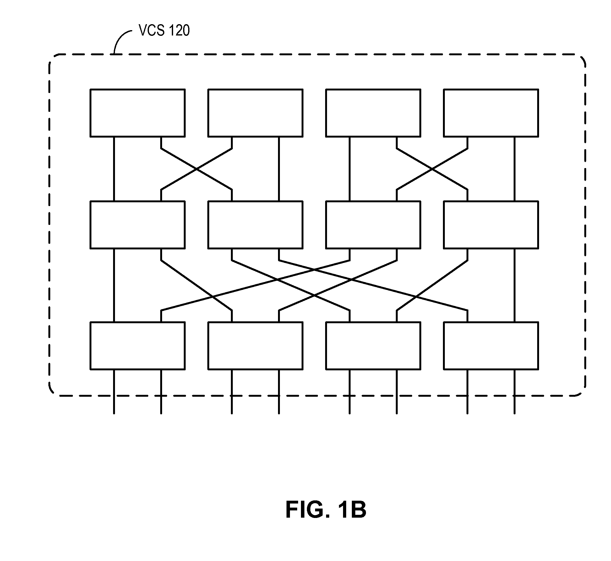
[0041]In embodiments of the present invention, the problem of building a versatile, cost-effective, and scalable switching system is solved by running a control plane with automatic configuration capabilities (such as the Fibre Channel control plane) over a conventional transport protocol, thereby allowing a number of switches form a switch cluster that can be represented as a single...


PUM


Abstract

One embodiment of the present invention provides a switch system. The switch includes a port to couple to a second switch and a control mechanism configured. During operation, the control mechanism receives from the second switch a set of configuration information. Based on the received configuration information, the control mechanism invites the second switch to join a virtual cluster switch.

Description


Claims


Application Information

Patent Timeline
Owner AVAGO TECH INT SALES PTE LTD
Learn More