Self-retaining sutures with bi-directional retainers or uni-directional retainers

a self-retaining suture and retainer technology, applied in the field of self-retaining sutures, can solve the problems of limiting the effectiveness of barbs, being rejected by the body rather than absorbed, and inflammation

Active Publication Date: 2011-11-24
CILAG GMBH INT
View PDF15 Cites 63 Cited by
  • Summary
  • Abstract
  • Description
  • Claims
  • Application Information

AI Technical Summary

Benefits of technology

[0016]In accordance with an embodiment of the present invention, each bi-directional retainer can be collapsed in either of two directions, depending upon the direction in which the retainer is deployed through tissue. In accordance with an embodiment, each retainer collapses in a direction opposite to the direction in which the retainer is deployed through tissue. Once a retainer is collapsed due to the retainer being deployed through tissue in a first direction, the retainer will substantially yield to motion of the elongated suture body within the tissue when the elongated suture body is drawn in the first direction, and will resist motion of the elongated suture body in a second direction generally opposite the first direction.
[0017]In accordance with an embodiment of the present invention, a shape of each retainer can be transformed in either of two manners, depending upon the direction in which the retainer is deployed through tissue. Once a retainer is transformed in shape due to the retainer being deployed through tissue in a first direction, the retainer will substantially yield to motion of the elongated suture body within the tissue when the elongated suture body is drawn in the first direction, and will resist motion of the elongated suture body in a second direction generally opposite the first direction. Once a retainer is transformed in shape due to the retainer being deployed through tissue in the second direction, the retainer will substantially yield to motion of the elongated suture body within the tissue when the elongated suture body is drawn in the second direction, and will resist motion of the elongated suture body in the first direction.

Problems solved by technology

In rare cases, bioabsorbable sutures can cause inflammation and be rejected by the body rather than absorbed.
One of the earlier patents describing a barbed suture is U.S. Pat. No. 3,716,058, which discloses a suture having one or more relatively rigid barbs at its opposite ends; the presence of the barbs just at the ends of the suture would limit the barbs' effectiveness.

Method used


Image

  • Self-retaining sutures with bi-directional retainers or uni-directional retainers
  • Self-retaining sutures with bi-directional retainers or uni-directional retainers
  • Self-retaining sutures with bi-directional retainers or uni-directional retainers

Examples


Embodiment Construction

[0037]Prior to setting forth the invention, it may be helpful to an understanding thereof to first set forth definitions of certain terms that are used hereinafter.

[0038]“Self-retaining system” refers to a self-retaining suture together with means for deploying the suture into tissue. Such deployment means include, without limitation, suture needles and other deployment devices as well as sufficiently rigid and sharp ends on the suture itself to penetrate tissue.

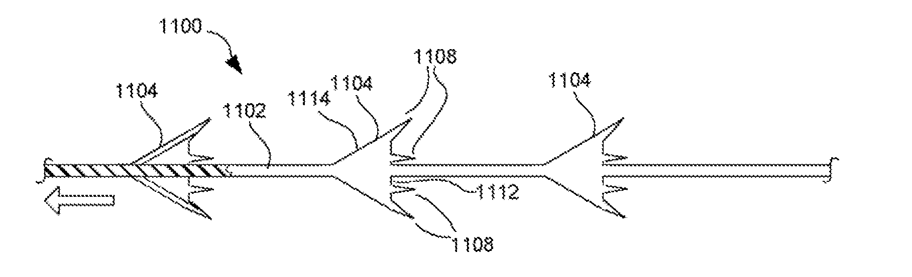
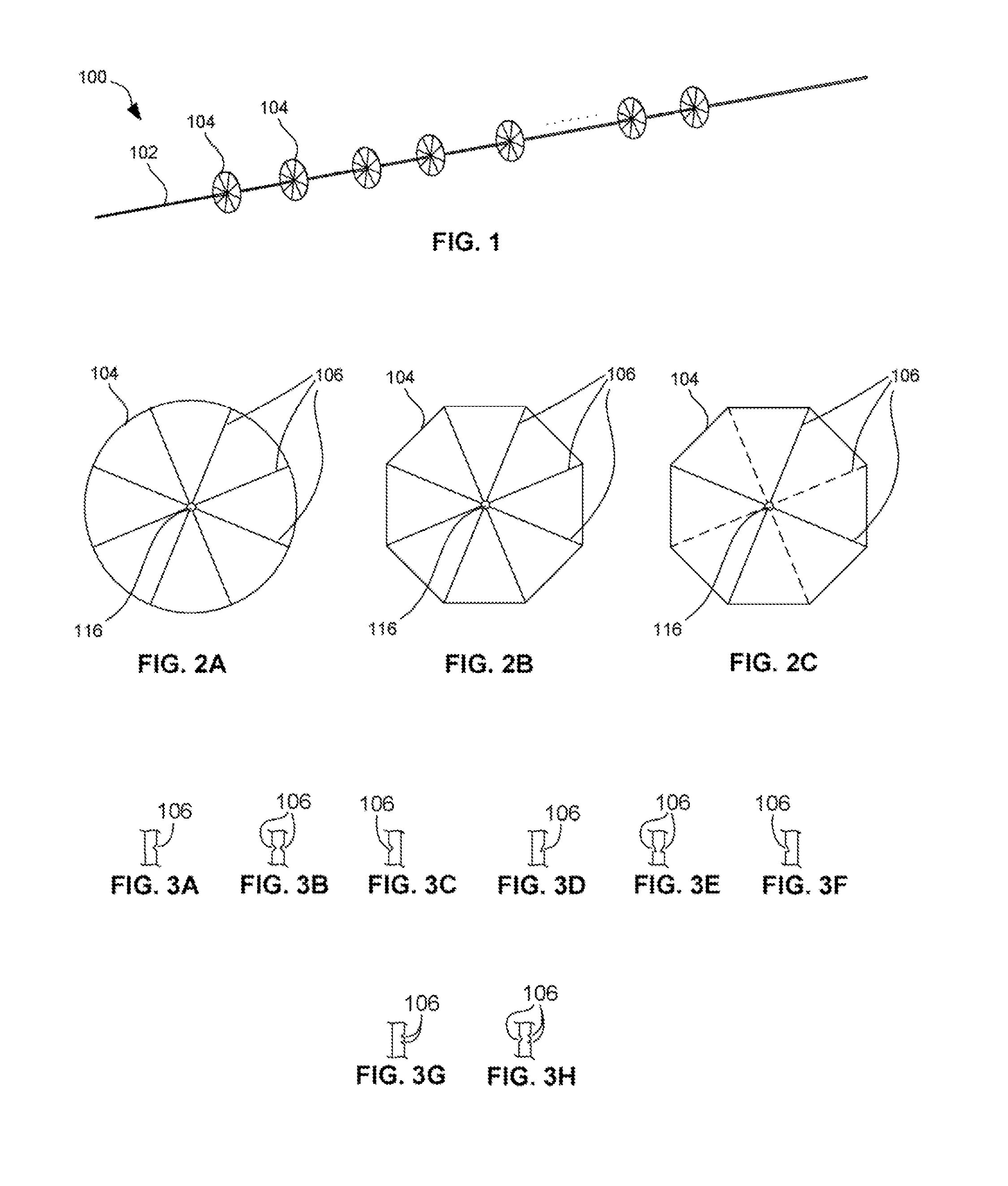
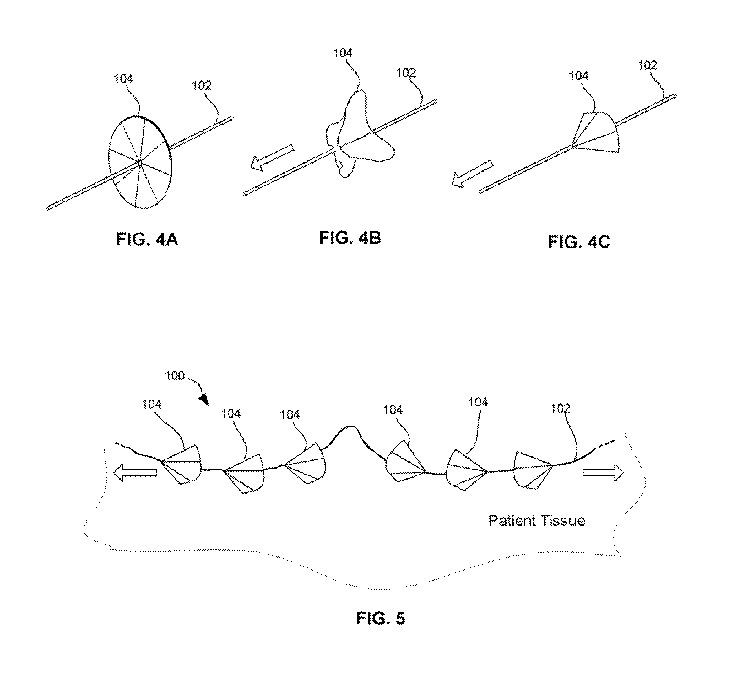
[0039]“Self-retaining suture” refers to a suture that does not require a knot or a suture anchor at its end in order to maintain its position into which it is deployed during a surgical procedure. These may be monofilament sutures or braided sutures, and are positioned in tissue in two stages, namely deployment and affixation, and include at least one tissue retainer.

[0040]“Tissue retainer” (or simply “retainer” or “barb”) refers to a suture element having a retainer body projecting from the suture body and a retainer end ad...


PUM


Abstract

Provided herein are sutures for use in a procedure applied to tissue, and methods for forming such sutures. Some sutures include bi-directional retainers, each of which can be deployed in two directions, but once deployed in one direction, resist motion in the opposite direction. Other sutures include uni-directional retainers that are conical in shape, and include tissue engaging protrusions that extend from edges and/or angled walls of the conical retainers.

Description

FIELD OF THE INVENTION[0001]The present invention relates generally to self-retaining sutures for surgical procedures, methods of manufacturing self-retaining sutures for surgical procedures, and their uses.BACKGROUND OF INVENTION[0002]Sutures are commonly used for closing or binding together wounds in human or animal tissue, such as skin, muscles, tendons, internal organs, nerves, and blood vessels. Sutures can be formed from non-absorbable material such as silk, nylon, polypropylene, or cotton, or alternatively sutures can be formed from bio-absorbable material such as, but not limited to, homopolymers and / or copolymers of glycolide, lactide, p-dioxanone and ε-caprolactone.[0003]Sutures typically consist of a filamentous suture thread with a needle with a sharp point (attachment of sutures and surgical needles is described in U.S. Pat. Nos. 3,981,307, 5,084,063, 5,102,418, 5,123,911, 5,500,991, 5,722,991, 6,012,216, and 6,163,948, and U.S. Patent Application Publication No. 2004 / 0...

Claims


Application Information

Patent Timeline
Patent Type & Authority Applications(United States)
IPC IPC(8): A61B17/04
CPCA61B17/06166A61B17/08A61B2017/081A61B2017/06176A61B2017/00526A61B17/04A61B17/064A61B2017/00349A61B2017/0461A61B2017/06142
Inventor GORALTCHOUK, ALEXEIDRUBETSKY, LEVCUMMINGS, GERALD F.HERRMANN, ROBERT A.NAIMAGON, ALEXANDER
Owner CILAG GMBH INT
Why Eureka
Try Eureka