
Flexible current sensor

a current sensor and flexible technology, applied in the direction of instruments, measurement devices, measurement using dc-ac conversion, etc., can solve the problem that conventional current sensors are difficult to use with different sizes or shapes of conductors

Inactive Publication Date: 2006-04-20
SIEMENS ENERGY & AUTOMATION INC
View PDF34 Cites 48 Cited by
  • Summary
  • Abstract
  • Description
  • Claims
  • Application Information

AI Technical Summary

Benefits of technology

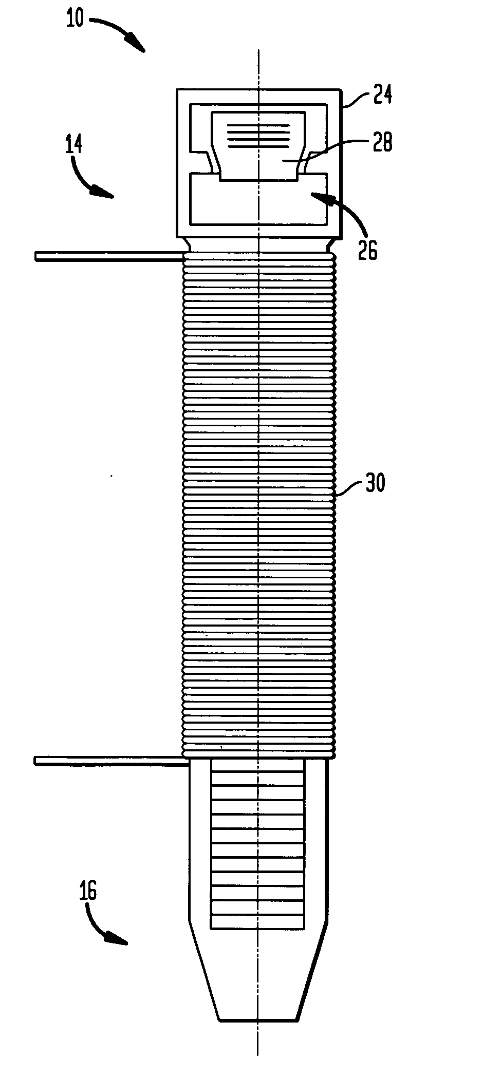
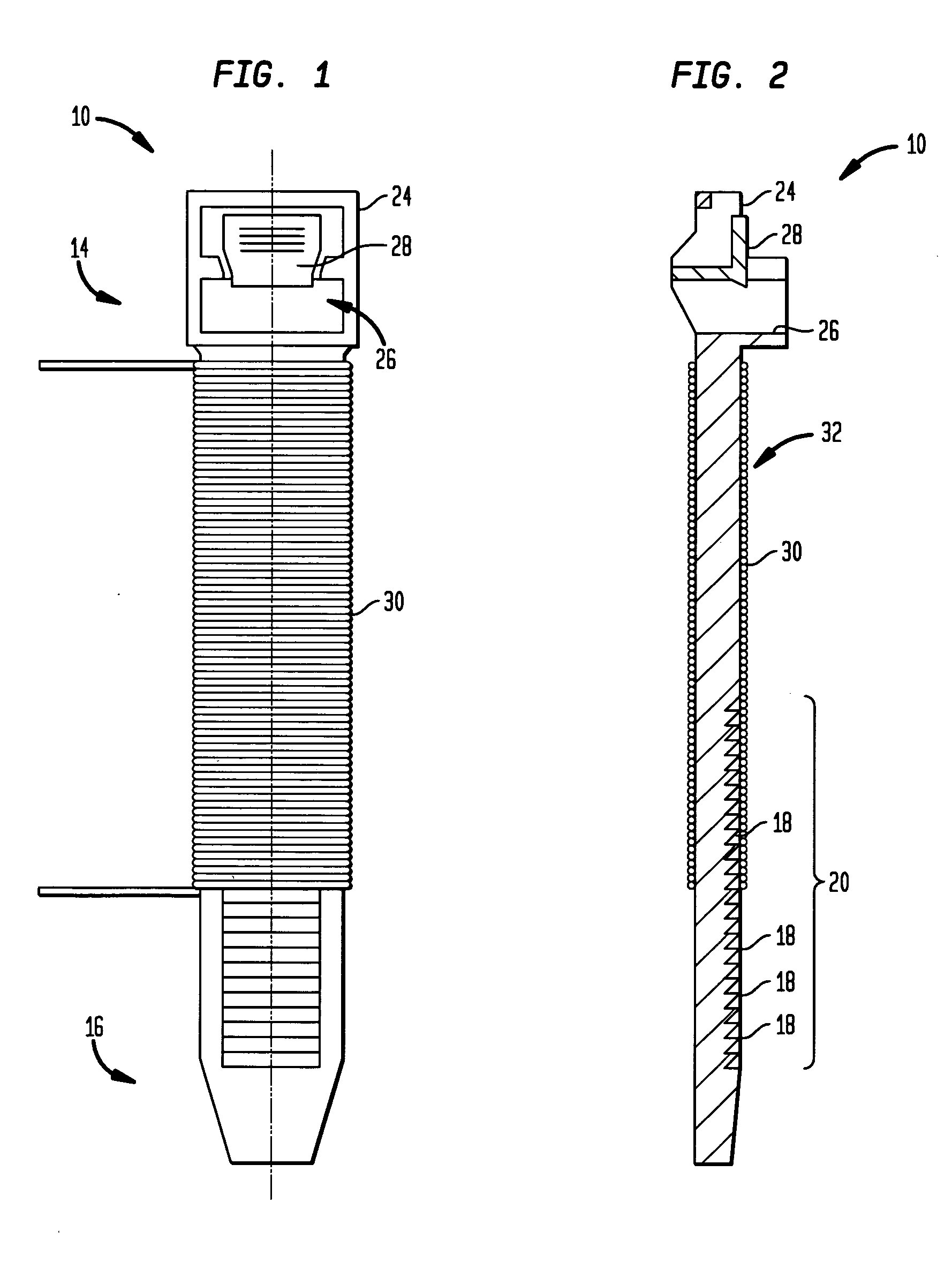
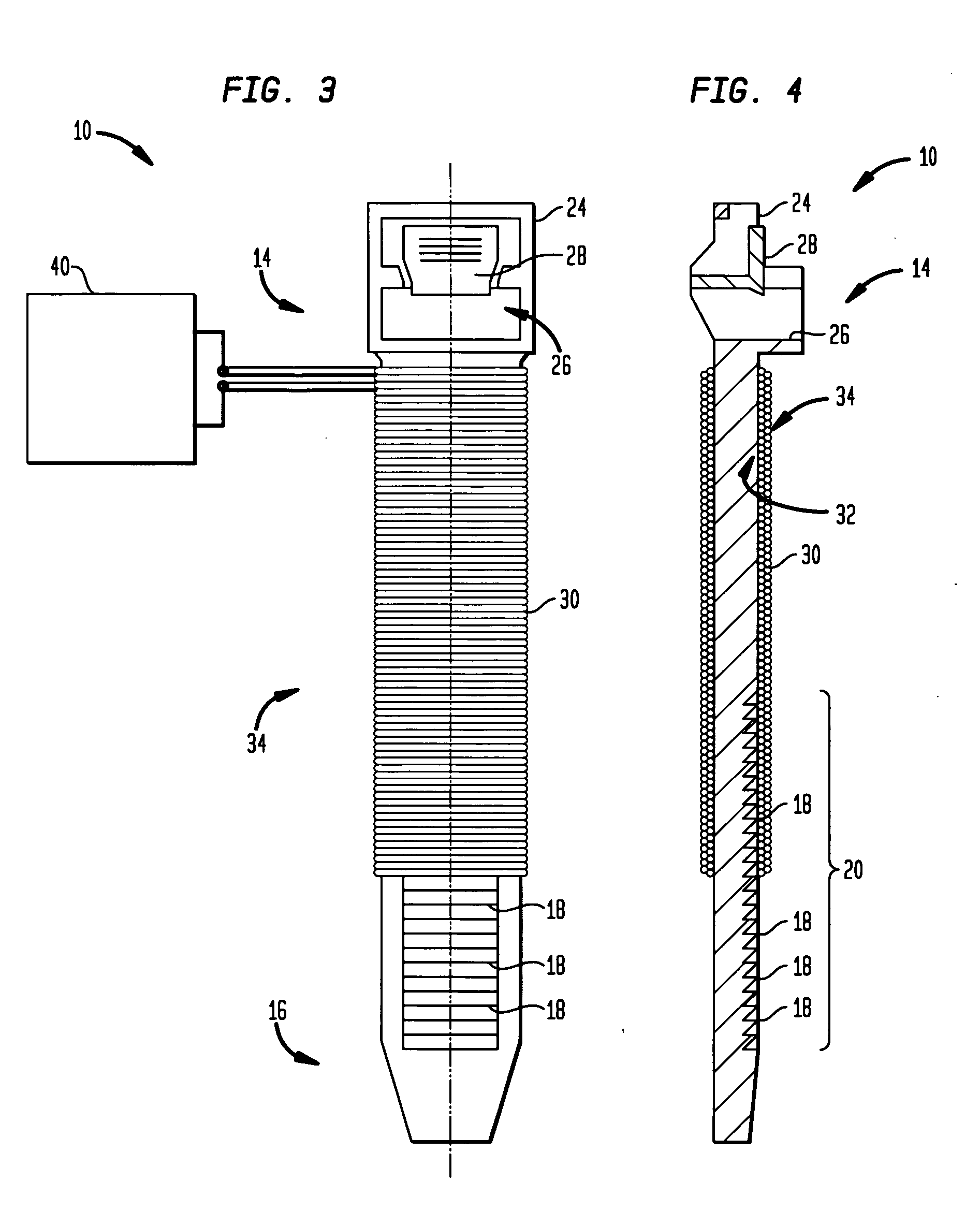
[0022] In use, an operator will place the flexible current sensor 10 on the conductor 5 in a perpendicular aspect to the longitudinal length of the conductor 5 to be monitored. The second end 16 of the flexible current sensor 10 is wrapped around the conductor 5 with the second end 16 inserted into the channel 26 formed in the locking head 24. The user pulls the second end 16 through the channel 26 to draw the flexible current sensor 10 against the conductor 5. Exemplary embodiments of a flexible current sensor 10 are illustrated in FIGS. 6, 7 and 8 showing the flexible current sensor 10 wrapped around various shaped conductors 5.

Problems solved by technology

Conventional current sensors are difficult to use with different size or shaped conductors.

Method used


Image

  • Flexible current sensor
  • Flexible current sensor
  • Flexible current sensor

Examples


Embodiment Construction

[0017] Referring to the figures, FIGS. 1 and 2 illustrate a flexible current sensor 10 for measuring a current in a conductor 5. The sensor 10 comprises a non-magnetic, flexible core member 12 having a first end 14 and a second end 16. The flexible core member 12 can be composed of a flexible material such as nylon, plastic, or a high modular elastomer. The flexible core member can be of any convenient length. It should be understood that the flexible core member 12 can be stored in a flat, straight manner when not looped around a conductor 5 as will be described below.

[0018] The disclosed flexible current sensor 10 has the characteristic of being able to be stored in a flat straight manner distinguishes the current sensor described from conventional current sensors that typically are rigid or if they have some flexibility do not lay in a flat straight manner. An additional characteristic of the disclosed flexible current sensor 10 is the variable diameter D of a loop formed by the...


PUM


Abstract

A method and a current sensor for measuring a current in a conductor. The sensor comprises a non-magnetic, flexible core member having a first end and a second end. A locking head having a channel therethrough is coupled to the first end of the core member. A first sensor conductor winding layer is mounted on the core member. Wherein the second end releasably engages the locking thread in the channel and adjustably configures the core member to surround the conductor as the second end is moved through the channel. In another embodiment the current sensor includes a locking tang within the channel and a plurality of sought tooth members on a portion of the core member and configured to selectively engage the locking tang as the second end of the core member is moved through the channel.

Description

BACKGROUND OF THE INVENTION [0001] The present invention relates to a sensor for measuring current in an electrical conductor, more particularly for a flexible current sensor. [0002] It is known to measure electric current in a conductor by measuring the generated field with a coil positioned around or in close proximity to the conductor being monitored. Such coils are known as a Rogowski Coil. The magnetic field caused by the current flowing in the monitored conductor induces a voltage between the ends of the coil sensor conductor in proportion to the current flowing in the monitored conductor. The induced voltage, or output signal of the Rogowski Coil is read by a signal processing circuit for further processing, such as for example, a microprocessor or voltage divider circuit. [0003] A typical current sensor coil is either a fixed annular closed loop or an unadjustable openable loop structure. The monitor conductor is threaded through the current sensor coil. Conventional current...

Claims


Application Information

Patent Timeline
Patent Type & Authority Applications(United States)
IPC IPC(8): G01R15/18
CPCG01R1/22G01R15/181
Inventor ZHANG, BINBILAC, MARIO
Owner SIEMENS ENERGY & AUTOMATION INC
Learn More