Handheld Tube Capper/Decapper

a technology for capping and decapping tubes, which is applied in the direction of caps, rotating screw stoppers, laboratory glassware, etc., and can solve the problems of large devices, bulky, expensive, and operabl

Active Publication Date: 2011-12-01
MATRIX TECH
View PDF2 Cites 21 Cited by
  • Summary
  • Abstract
  • Description
  • Claims
  • Application Information

AI Technical Summary

Problems solved by technology

However, these devices are large, bulky, costly, and operable only with respect to all caps from all tubes within the rack.

Method used


Image

  • Handheld Tube Capper/Decapper
  • Handheld Tube Capper/Decapper
  • Handheld Tube Capper/Decapper

Examples


Embodiment Construction

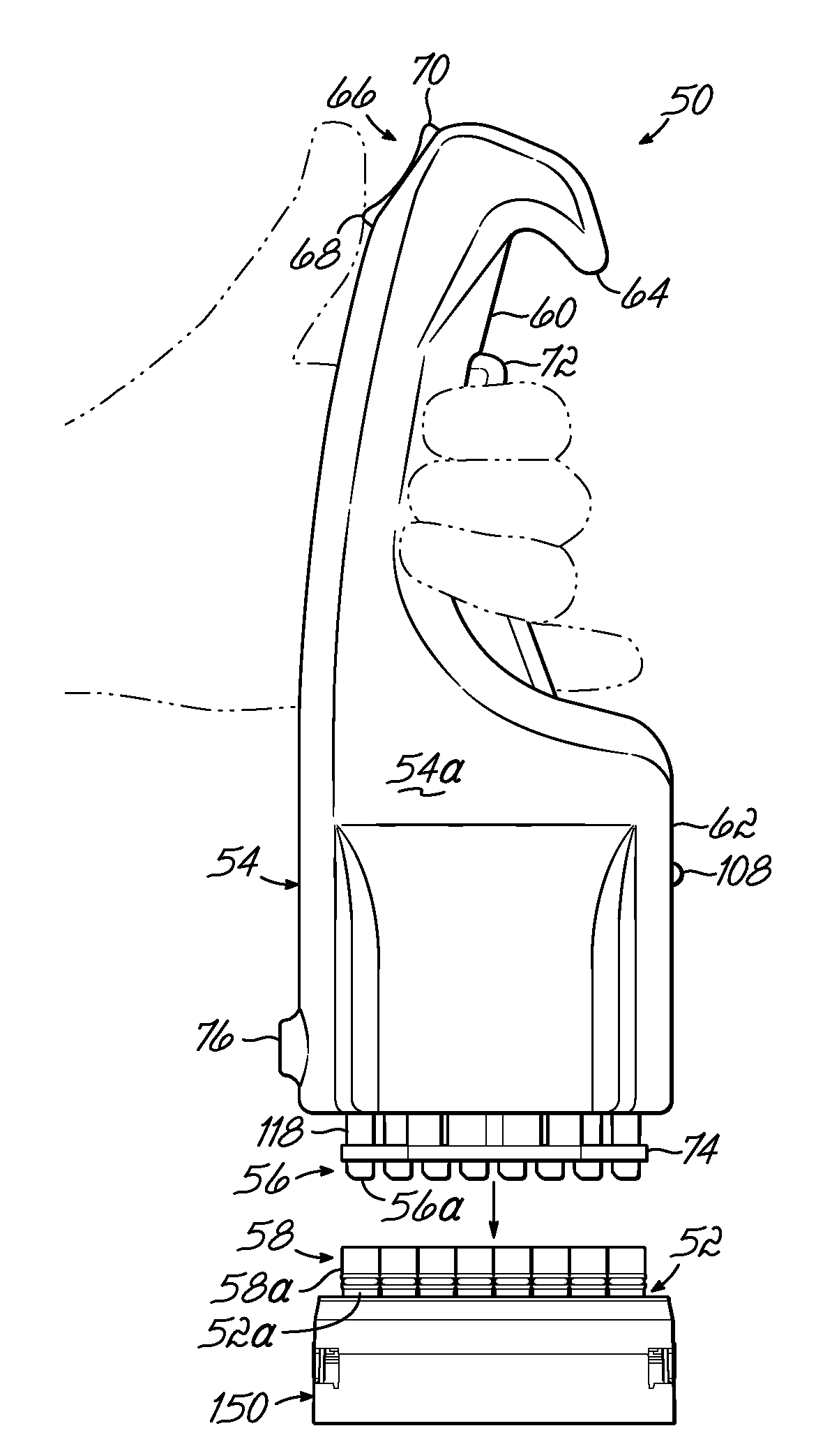
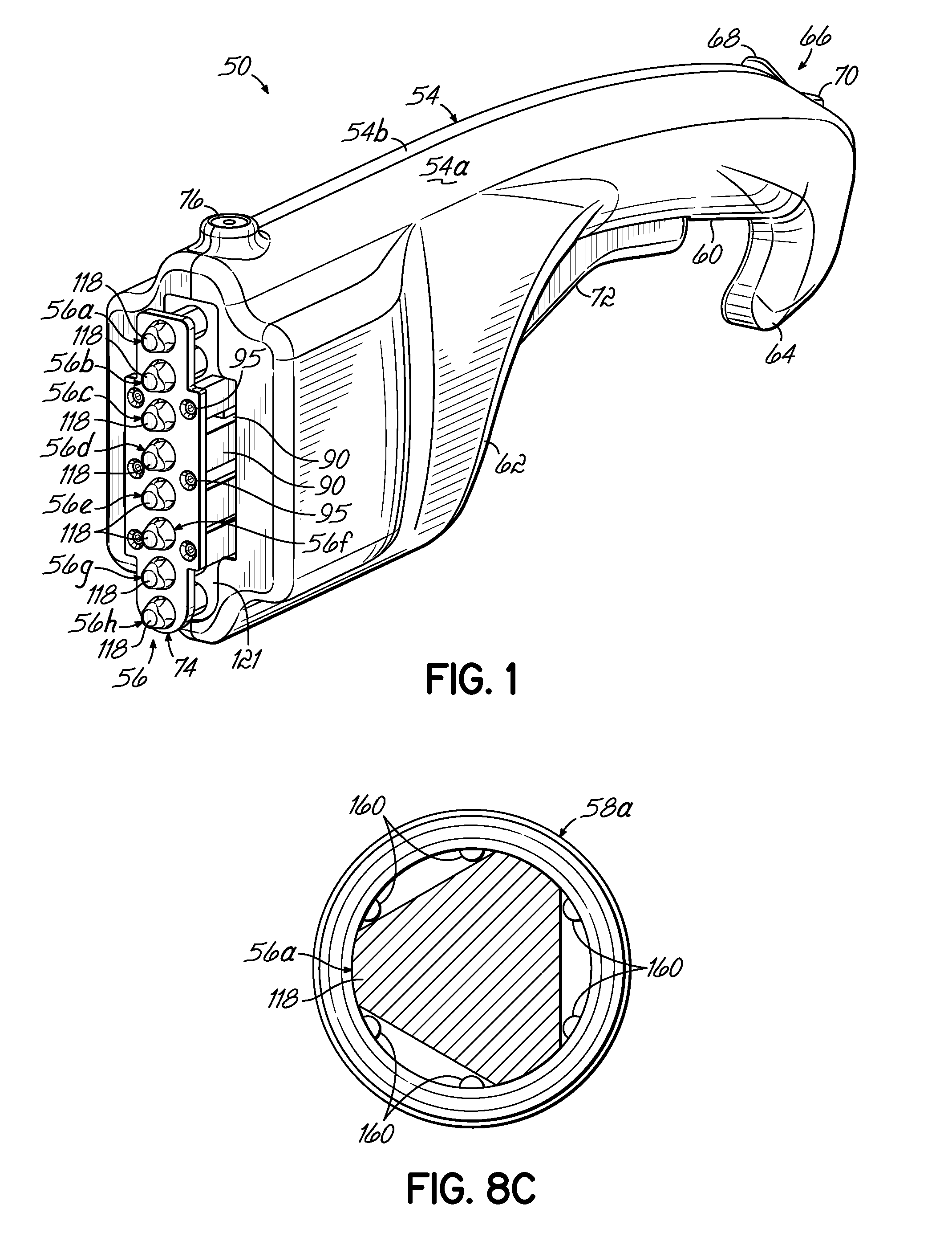
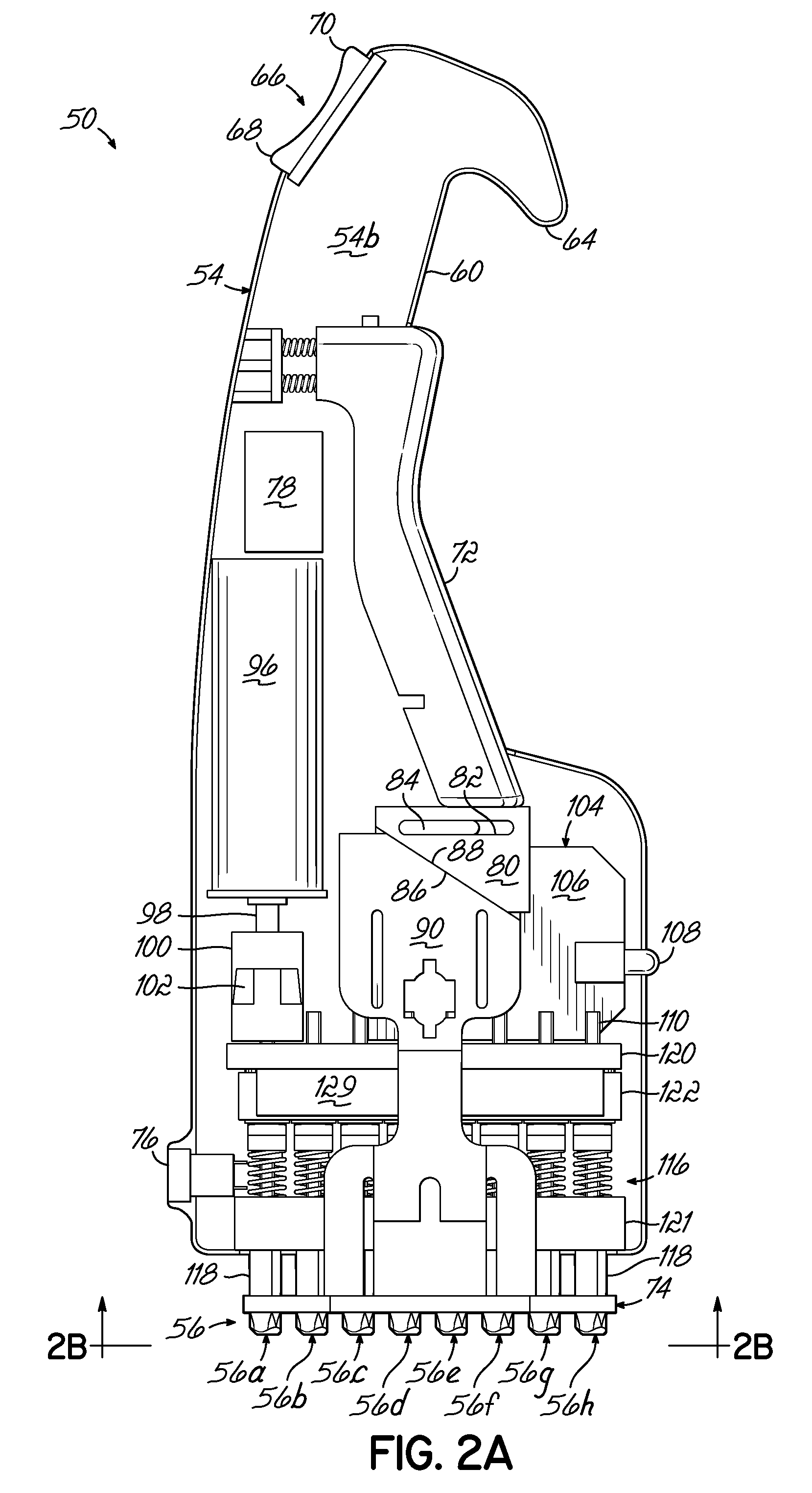
[0029]Referring now to the figures, and to FIG. 1 in particular, a handheld device 50 according to one embodiment of the present invention is shown for capping and decapping a one-dimensional array of receptacles that may be used to hold and / or store a sample. Receptacles may vary in size and shape according to the particular application and may include a one-dimensional array of tubes 52 such as those shown in FIG. 6, by way of example and without limitation thereto. The device 50 includes a handheld housing 54 that supports a one-dimensional array of spindles 56 that are configured to cooperate with caps 58a-58h (FIG. 6) as will be described in detail below.

[0030]The housing 54 may include an ergonomic design that facilitates grasping and operation of the device 50 by a wide range of user hand sizes as shown in FIG. 7. In this way, the handheld device 50 may be manually manipulated by a user in a plurality of different orientations during capping and decapping operations.

[0031]In ...


PUM


Abstract

A tube capper and decapper and method of using the same. The tube capper includes a handheld housing that supports a one-dimensional array of spindles. Each spindle is shaped to receive a cap. A drive mechanism rotates each spindle of the one-dimensional array in unison for capping or decapping a corresponding one-dimensional array of tubes.

Description

FIELD OF THE INVENTION[0001]The present invention relates generally to devices and methods for capping and decapping tubes and, more specifically, to a device and method for capping and decapping an array of receptacles, such as microtubes.BACKGROUND OF THE INVENTION[0002]Chemical investigations are often carried out on a micro-volume scale within microtubes that are configured to hold, by way of example, 0.25 mL to 2 mL of volume. These tubes allow the investigator to test several combinations or reactions at a single time without large volumes or expense. The tubes may be capped and stored as arrays in racks of 16 to 96 tubes each. Conventionally, capping and decapping of tubes was accomplished individually by hand when the addition of reagents or withdrawal of the sample was necessary. Recently, multi-channel pipetters have allowed technicians to work simultaneously with multiple tubes at a time. Still, capping and decapping was accomplished manually.[0003]More recently, table to...

Claims


Application Information

Patent Timeline
Patent Type & Authority Applications(United States)
IPC IPC(8): B67B3/00B67B7/00
CPCB01L3/50853B01L99/00G01N2035/0405B67B3/2006B01L2300/042
Inventor KOHANSKI, JONATHANSEGUIN, DANIEL J.DICARLO, JOSEPHFRANZINI, LOUIS
Owner MATRIX TECH
Why Eureka
Try Eureka