Implantable wireless sensor for pressure measurement within the heart

a wireless sensor and implanted technology, applied in the field ofchronically implanted sensors, can solve the problems of limiting its use to acute settings, the technique used to fabricate the sensors is not suitable for the miniaturization necessary for its configuration, and the fabrication method used to manufacture them is not sufficien

Inactive Publication Date: 2005-02-15
ST JUDE MEDICAL LUXEMBOURG HLDG II S A R L SJM LUX II
View PDF21 Cites 626 Cited by
  • Summary
  • Abstract
  • Description
  • Claims
  • Application Information

AI Technical Summary

Benefits of technology

The present invention describes a sensor that can be fabricated using micro-machining techniques and can be implanted into the human body using non-surgical methods for the measurement of physical parameters. This sensor is fabricated using MicroElectroMechanical Systems (MEMS) technology, which allows the creation of a flexible device that is small, accurate, precise, durable, robust, biocompatible, radiopaque and insensitive to changes in body chemistry, biology or external pressure. This device will not require the use of wires to relay pressure information externally nor need an internal power supply to perform its function.
The above methods lend themselves to the creation of small and simple to manufacture hand-held electronic devices that can be used without complication.
Thus, this patent discloses a simple method of monitoring the pressure within the human heart by inserting a pressure transducer using a catheter and using a small, hand-held read device to measure the pressure easily, safely, inexpensively and accurately. It also includes a method of introducing the sensor into the body by using the steps of folding or rolling the sensor into a cylinder, loading it into a catheter and deploying into the heart by allowing it to unroll or unfold, either by itself or facilitated by the incorporation of a super-elastic alloy component. The same super-elastic element also provides the means to permanently securing the device to the interior of the heart.
In a further alternative delivery procedure the sensor can be loaded into the annular space between the inner and outer catheters by inserting the sensor into a longitudinal slit cut into the outer catheter and attaching a tab on the sensor's surface into a slot cut into the inner coaxial catheter. By rotation of the inner tube, the sensor will be retracted through the slit and positioned in the annular space between the two tubes. To deploy the device, the rotation of the inner tube is reversed and the sensor emerges through the slit of the outer catheter. There are two specific advantages to this deployment mechanism. First, the sensor can be packaged and stored in a flat configuration. This is desirable since long term storage in a pre-loaded curved geometry could make it more difficult for the sensor to re-establish the flat arrangement that is optimal for effective electromagnetic inductive coupling with the external read-out unit. The second advantage is that by cutting the longitudinal slit at angle that is offset from the main axis of the outer tube, the sensor will be biased into a planar configuration as it is forced through the slit during the deployment process.

Problems solved by technology

The drawback of this type of sensor is that there must be a physical connection between the sensor and the external device, thus limiting its use to acute settings.
The primary limitation to these type of sensors are the fabrication methods used to manufacture them do not provide sufficient miniaturization to allow them to be introduced and implanted into the heart using non-surgical, catheter based techniques.
The primary limitation of many of these inventions is that the techniques used to fabricate the sensors do not lend themselves to the miniaturization necessary for it to be configured as an implantable medical device.
The resulting sensors are inherently rigid severely limiting the ability to manipulate them into temporarily small packages that would provide the means for non-surgical implantation into the human body.
These sensors suffer from many of the limitations already mentioned with the additional concerns that they require either the addition of a power source to operate the device or the need for a physical connection to a device capable of translating the sensor output into a meaningful display of a physiologic parameter.
The device embodied by the Chubbuck patent is manufactured using conventional techniques, thus requiring surgical implantation and thus limiting its applicability to areas that are easily accessible to surgery (i.e., skull).

Method used


Image

  • Implantable wireless sensor for pressure measurement within the heart
  • Implantable wireless sensor for pressure measurement within the heart
  • Implantable wireless sensor for pressure measurement within the heart

Examples


Embodiment Construction

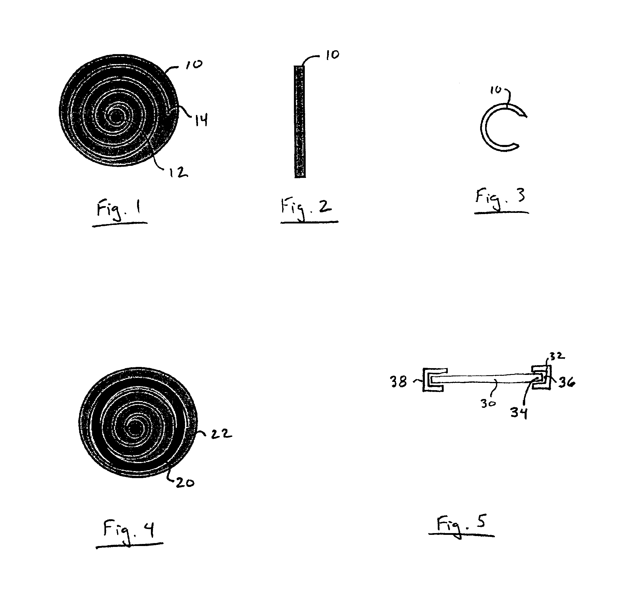
The invention can perhaps be better understood by referring to the drawings. One embodiment of a sensor according to the invention is shown in FIGS. 1, 2, and 3, where a disc-shaped sensor 10 comprises a capacitor disk 12 and a wire spiral 14. FIG. 2 is a lateral view of sensor 10, and FIG. 3 is a lateral view of sensor 10 in a folded configuration for insertion. The fact that sensor 10 is sufficiently flexible to be folded as shown in FIG. 4 is an important aspect of the invention.

In FIG. 4 a ring 20 comprised of a shape memory alloy such as nitinol has been attached to, for example, with adhesive, or incorporated into, for example, layered within, a sensor 22.

FIG. 5 is a lateral cross-sectional view of a circular sensor 30 having a ring 32 comprised of a shape memory alloy such as nitinol encompassing the outer edge 34 of sensor 30. Ring 32 preferably is attached to outer edge 34 by a suitable physiologically acceptable adhesive 36, such as an appropriate epoxy or cyanoacrylate ma...


PUM


Abstract

The progress of a endovascular cardiac repair can be monitored by inserting a pressure transducer sensor using a catheter into a chamber of the heart during endovascular repair and then using a small, hand-held read out device to measure pressure easily, safely, inexpensively and accurately. In one aspect a sensor is introduced into the body by the steps of folding or rolling the sensor into a cylinder, loading it into a catheter, and deploying into the heart chamber by allowing it to unroll or unfold, either by itself or facilitated by the incorporation of a super-elastic alloy component.

Description

FIELD OF THE INVENTIONThis invention relates to chronically implanted sensors for wirelessly sensing pressure, temperature and other physical properties within the human body. More particularly, the invention concerns a wireless, un-powered micromachined pressure sensor that can be delivered using endovascular techniques to the interior of the human heart.BACKGROUND OF THE INVENTIONThe measurement of blood pressure within the human heart provides critical information regarding the organ's function. Many methods and techniques have been developed to give physicians with the ability to monitor heart function to properly diagnose and treat various diseases and medical conditions. For example, a sensor or transducer placed within the chambers of the heart can be used to record variations in blood pressure based on physical changes to a mechanical element within the sensor. This information is then transferred from the sensor to external device that is capable of translating the data fro...

Claims


Application Information

Patent Timeline
Patent Type & Authority Patents(United States)
IPC IPC(8): A61B5/00A61B5/0215
CPCA61B5/0215A61B5/0031
Inventor FONSECA, MICHAELALLEN, MARKSTERN, DAVIDWHITE, JASONKROH, JASON
Owner ST JUDE MEDICAL LUXEMBOURG HLDG II S A R L SJM LUX II
Why Eureka
Try Eureka