Rotational parabolic antenna with various feed configurations

a parabolic antenna and rotational technology, applied in the field of parabolic antennas with various feed configurations, can solve the problems of ground clutter, under-sample the atmosphere, and difficult methods to maintain and debug

Active Publication Date: 2011-12-01
RADIOMETRICS CORP
View PDF34 Cites 184 Cited by
  • Summary
  • Abstract
  • Description
  • Claims
  • Application Information

AI Technical Summary

Benefits of technology

[0012]According to another aspect, a circle is traced out by beam positions of the antenna, and data is collected at one of four, eight, sixteen, or

Problems solved by technology

However, among other things, these two methods create antenna beams which produce relatively high side-lobe antenna patterns (since it is difficult to amplitude taper these antennas), and have phase-shifters (RF switches used for pointin

Method used


Image

  • Rotational parabolic antenna with various feed configurations
  • Rotational parabolic antenna with various feed configurations
  • Rotational parabolic antenna with various feed configurations

Examples


Embodiment Construction

[0036]The exemplary embodiments set forth below represent the necessary information to enable those skilled in the art to practice the invention. Upon reading the following description in light of the accompanying drawing figures, those skilled in the art will understand the concepts of the invention and will recognize applications of these concepts not particularly addressed herein. It should be understood that these concepts and applications fall within the scope of the disclosure and the accompanying claims.

[0037]Note that at times the system of the present disclosure is described as performing a certain function. However, one of ordinary skill in the art would know that the program is what is performing the function rather than the entity of the system itself.

[0038]Although aspects of one implementation of the present disclosure are depicted as being stored in memory, one skilled in the art will appreciate that all or part of systems and methods consistent with the present inven...


PUM


Abstract

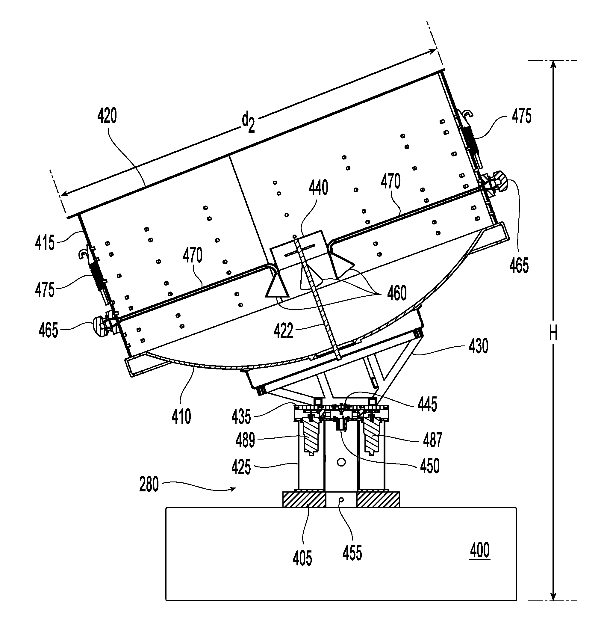
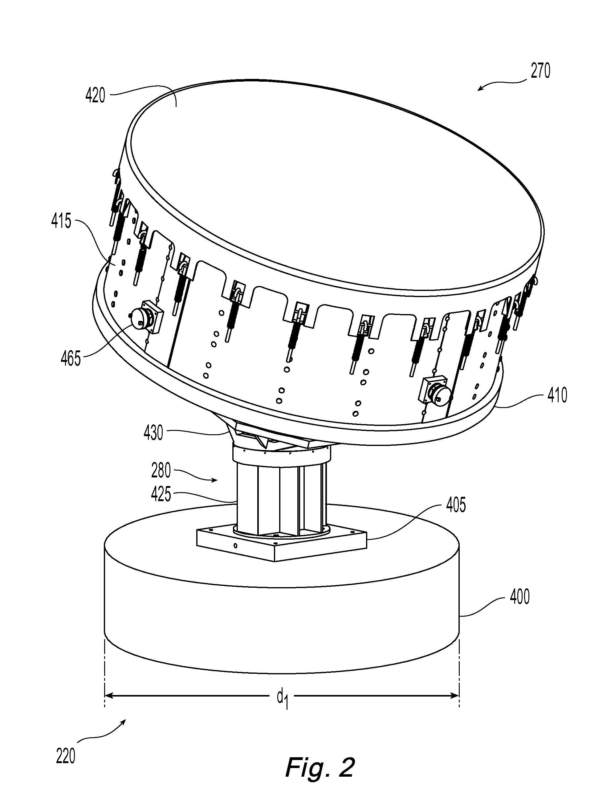
A rotational antenna includes a stationary feed which is disposed in a substantially vertical orientation. A parabolic dish is rotationally mounted about the stationary feed in a state of being tipped with respect to the stationary, substantially vertically oriented feed. The rotational parabolic antenna may alternatively be provided with a rotating radio frequency (RF) and acoustic feed. Other embodiments are disclosed.

Description

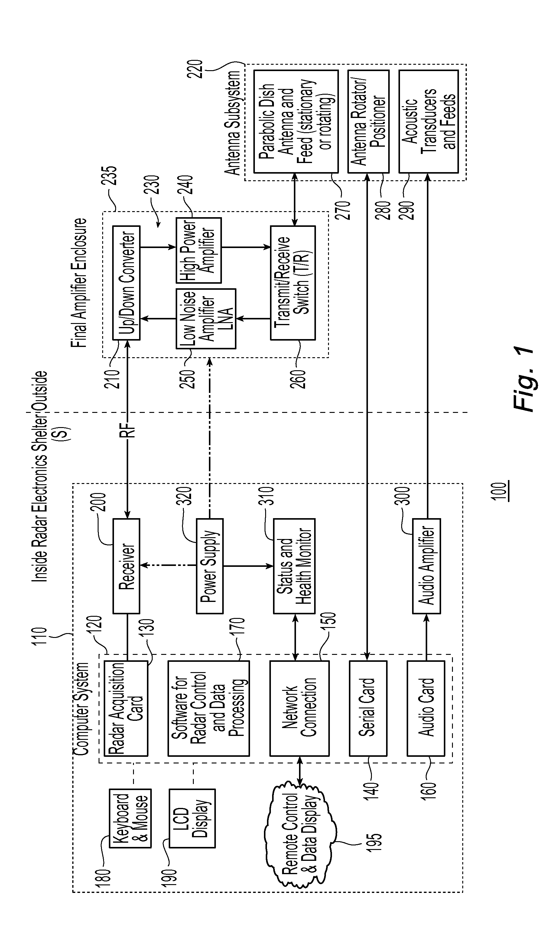
FIELD OF THE INVENTION[0001]The present disclosure relates to antenna systems and, more particularly, to a rotational parabolic antenna with various feed configurations. The feed configurations may include a rotational parabolic antenna with a fixed, either prime focus or off-center feed (the latter also called off-set feed), as well as a rotational parabolic antenna with a rotating radio frequency (RF) and acoustic feed.BACKGROUND OF THE INVENTION[0002]In general, there are various ways to create antenna beams required in, for example, radar wind profiling. One way is to use a micro-strip patch phased array. Another way is to use multiple antennas such as coaxial-collinear elements (“sticks”) in a perpendicular array or with three or five panels. Commercial wind profilers have relied primarily on these two methods. However, among other things, these two methods create antenna beams which produce relatively high side-lobe antenna patterns (since it is difficult to amplitude taper th...

Claims


Application Information

Patent Timeline
IPC IPC(8): G01S13/95H01Q3/00
CPCG01S13/951H01Q3/08H01Q3/02H01Q19/134G01S13/95H01Q19/132Y02A90/10
Inventor MCLAUGHLIN, SCOTT ANDREWSLOAN, MEGAN MAUREENLAU, ELIAS MOISES
Owner RADIOMETRICS CORP
Why Eureka
Try Eureka