Scroll machine

a roller machine and compressor technology, applied in the field of compressors, can solve the problems of inefficient compressor operation and compressor may also run inefficiently

Active Publication Date: 2011-12-01
COPELAND LP
View PDF3 Cites 41 Cited by
  • Summary
  • Abstract
  • Description
  • Claims
  • Application Information

AI Technical Summary

Problems solved by technology

If the scrolls axially separate from one another, an internal leakage is formed between the compression pockets, causing in

Method used


Image

  • Scroll machine
  • Scroll machine
  • Scroll machine

Examples


Embodiment Construction

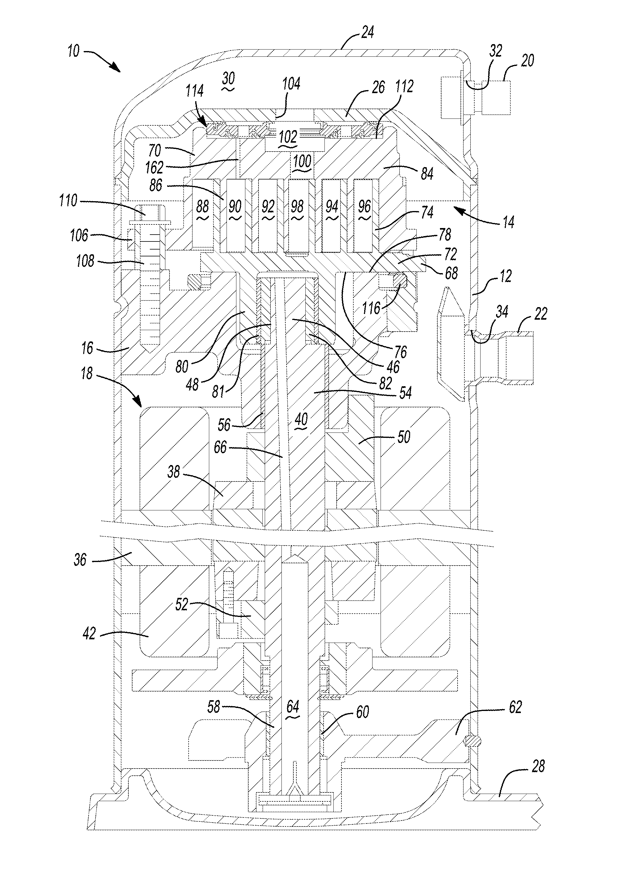
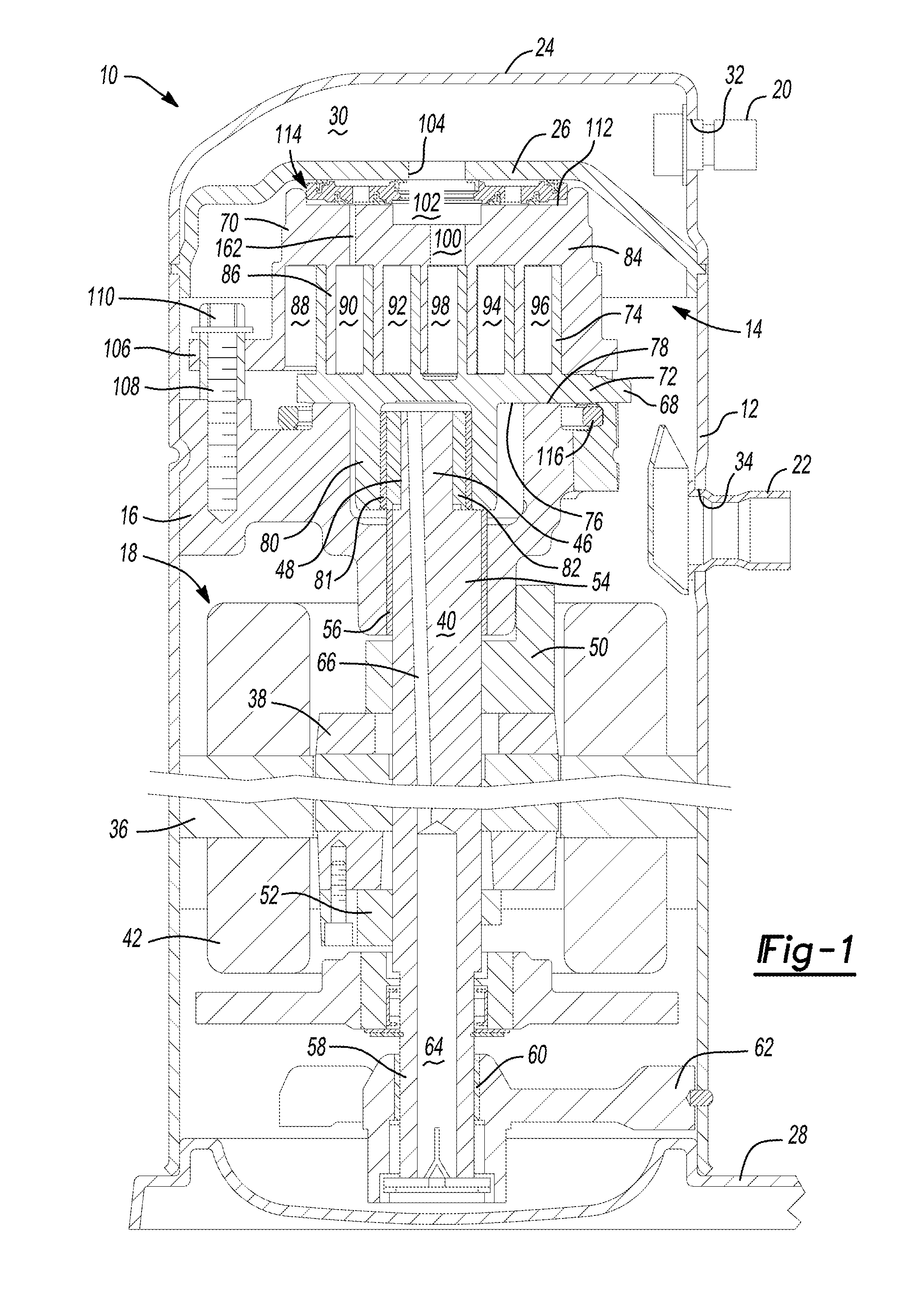
is a fragmentary sectional view of another compressor according to the present disclosure;

[0024]FIG. 13 is a fragmentary sectional view of another compressor according to the present disclosure the compressor in a first operating state;

[0025]FIG. 14 is a fragmentary sectional view of the compressor of FIG. 13 in a second operating state;

[0026]FIG. 15 is a fragmentary sectional view of another compressor according to the present disclosure the compressor in a first operating state;

[0027]FIG. 16 is a fragmentary sectional view of the compressor of FIG. 15 in a second operating state;

[0028]FIG. 17 is a fragmentary sectional view of another compressor according to the present disclosure with the compressor in a first operating state;

[0029]FIG. 18 is a fragmentary sectional view of the compressor of FIG. 17 in a second operating state; and

[0030]FIG. 19 is a graphical illustration of compressor operating conditions.

DETAILED DESCRIPTION

[0031]The following description is merely exemplary in...


PUM


Abstract

A compressor includes a shell, a compression mechanism, and an axial biasing system. The shell defines a first passage forming a first discharge passage. The compression mechanism includes first and second scroll members meshingly engaged with one another and forming a series of compression pockets. The first scroll member includes a second discharge passage. The axial biasing system includes a biasing member having first and second surfaces generally opposite one another. The first surface includes a first radial surface area exposed to an intermediate pressure from one of the compression pockets and a second radial surface area exposed to a discharge pressure. The second surface includes a third radial surface area exposed to the intermediate pressure. The biasing member is axially displaceable between first and second positions. The biasing member axially engages the first scroll member when in the first position.

Description

CROSS-REFERENCE TO RELATED APPLICATIONS[0001]This application is a continuation of U.S. patent application Ser. No. 12 / 355,206 filed on Jan. 16, 2009 which claims the benefit of U.S. Provisional Application No. 61 / 021,410 filed on Jan. 16, 2008. The entire disclosure of each of the above applications are incorporated herein by reference.FIELD[0002]The present disclosure relates to compressors, and more specifically to compressor seal assemblies.BACKGROUND[0003]The statements in this section merely provide background information related to the present disclosure and may not constitute prior art.[0004]A typical scroll compressor has first and second scrolls. In operation, the vanes of the first and second scrolls meshingly engage one another and form compression pockets. As these compression pockets capture and compress gas, they produce an axial separating force that urges the scrolls axially apart from one another. If the scrolls axially separate from one another, an internal leakag...

Claims


Application Information

Patent Timeline
IPC IPC(8): F04C18/04
CPCF04C18/0215F04C23/008F04C29/124F04C28/24F04C27/005
Inventor SEIBEL, STEPHEN M.STOVER, ROBERT C.AKEI, MASEO
Owner COPELAND LP
Why Eureka
Try Eureka