Dual seam electric resistance welded tubes

a technology of electric resistance and welded tubes, which is applied in the direction of welding with roller electrodes, manufacturing tools, mechanical equipment, etc., can solve the problems of high equipment cost and inferior products, and achieve the effect of reducing the convergence angl

Active Publication Date: 2011-12-22
DFI
View PDF4 Cites 8 Cited by
  • Summary
  • Abstract
  • Description
  • Claims
  • Application Information

AI Technical Summary

Problems solved by technology

In general, resistance welding methods are efficient and cause little pollution, but their applications are limited to relatively thin materials and the equipment cost can be high.
However, excessive bending or twisting will result in an inferior product, particularly as the diameter of tube becomes larger.

Method used


Image

  • Dual seam electric resistance welded tubes
  • Dual seam electric resistance welded tubes
  • Dual seam electric resistance welded tubes

Examples


Embodiment Construction

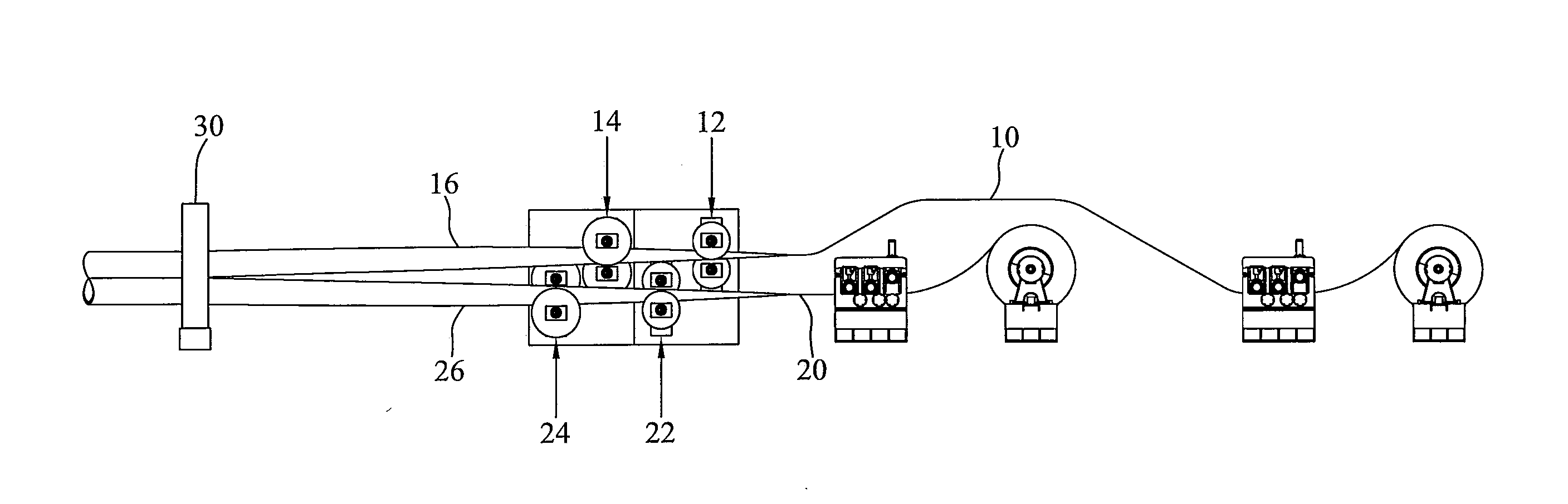
[0014]The invention relates to a method and apparatus of forming a dual seam welded tubular product. When describing the present invention, all terms not defined herein have their common art-recognized meanings. To the extent that the following description is of a specific embodiment or a particular use of the invention, it is intended to be illustrative only, and not limiting of the claimed invention. The following description is intended to cover all alternatives, modifications and equivalents that are included in the spirit and scope of the invention, as defined in the appended claims.

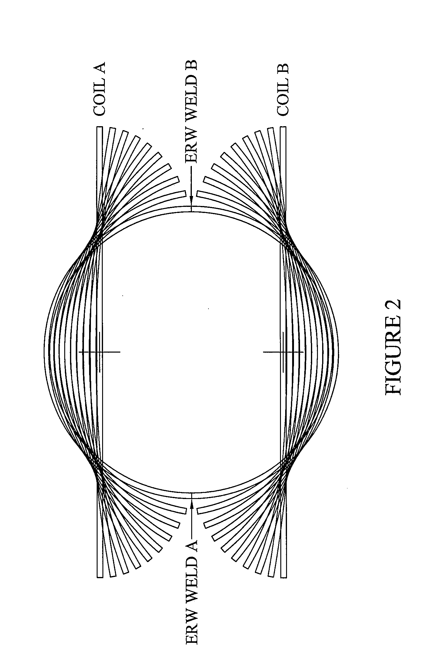
[0015]In general terms, one aspect of the invention comprises a method of continuously forming a dual seam welded tubular product, comprising the steps of:[0016](a) providing two coils of sheet metal material;[0017](b) uncoiling the two coils and forming the material into opposing sections, each having a generally semi-circular cross-section;[0018](c) bringing the two opposing sections together at a...


PUM

PropertyMeasurementUnit
convergence angleaaaaaaaaaa
diameteraaaaaaaaaa

Abstract

A method of continuously forming a dual seam welded tubular product includes the steps of providing two coils of sheet metal material, uncoiling the two coils and forming the material into opposing sections, bringing the two opposing sections together at a convergence angle of less than about 4°; and welding the two seams created between the two opposing sections. An apparatus is configured to bring the sections together at a convergence angle less than about 4° to produce the tubular product. The tubular product may have a diameter greater than 26 inches.

Description

CROSS REFERENCE TO RELATED APPLICATIONS[0001]This application claims the priority benefit of U.S. Provisional Application No. 61 / 329,721 filed on Apr. 30, 2010 entitled “Dual Seam Electric Resistance Welded Tubes”, the entire contents of which are incorporated herein by reference.FIELD OF THE INVENTION[0002]The present invention is directed to methods and apparatuses for forming dual seam welded tubes.BACKGROUND[0003]Electric resistance welding (ERW) refers to a group of welding processes such as spot and upset welding that produce coalescence of faying surfaces where heat to form the weld is generated by the resistance of the welding current through the workpieces. Some factors influencing heat or welding temperatures are the proportions of the workpieces, the electrode materials, electrode geometry, electrode pressing force, weld current and weld time. Small pools of molten metal are formed at the point of greatest electrical resistance (the connecting surfaces) as a high current ...

Claims


Application Information

Patent Timeline
Patent Type & Authority Applications(United States)
IPC IPC(8): F16L9/17B23K31/02
CPCB23K11/0873B21C37/08B21C37/0803B21B1/38B21C37/083B23K11/062
Inventor BERUBE, ERIC
Owner DFI
Why Eureka
Try Eureka