
Gas turbine system having premixed injector vanes

a gas turbine and injector valve technology, applied in the field of gas turbine reheating, can solve the problems of reducing the work output of each successive turbine section, reducing the pressure and temperature of the gas,

Active Publication Date: 2011-12-29
GENERAL ELECTRIC CO
View PDF5 Cites 62 Cited by
  • Summary
  • Abstract
  • Description
  • Claims
  • Application Information

AI Technical Summary

Problems solved by technology

Unfortunately, as the gases move from one turbine section to the next, the pressure and temperature of the gases decrease as each turbine section extracts work from the flow, generally reducing the work output of each successive turbine section.

Method used


Image

  • Gas turbine system having premixed injector vanes
  • Gas turbine system having premixed injector vanes
  • Gas turbine system having premixed injector vanes

Examples


Embodiment Construction

[0021]One or more specific embodiments of the present invention will be described below. In an effort to provide a concise description of these embodiments, all features of an actual implementation may not be described in the specification. It should be appreciated that in the development of any such actual implementation, as in any engineering or design project, numerous implementation-specific decisions must be made to achieve the developers' specific goals, such as compliance with system-related and business-related constraints, which may vary from one implementation to another. Moreover, it should be appreciated that such a development effort might be complex and time consuming, but would nevertheless be a routine undertaking of design, fabrication, and manufacture for those of ordinary skill having the benefit of this disclosure.

[0022]When introducing elements of various embodiments of the present invention, the articles “a,”“an,”“the,” and “said” are intended to mean that ther...


PUM


Abstract

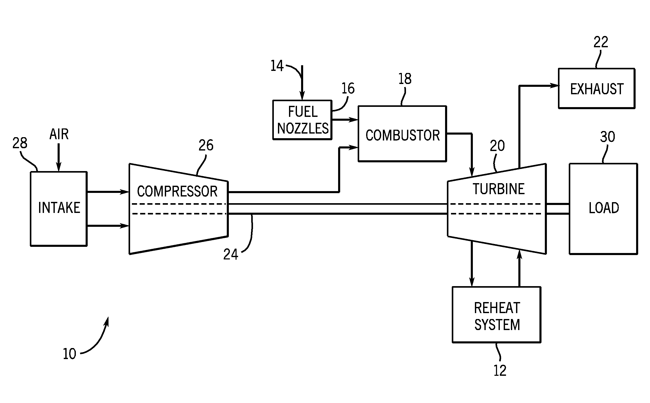
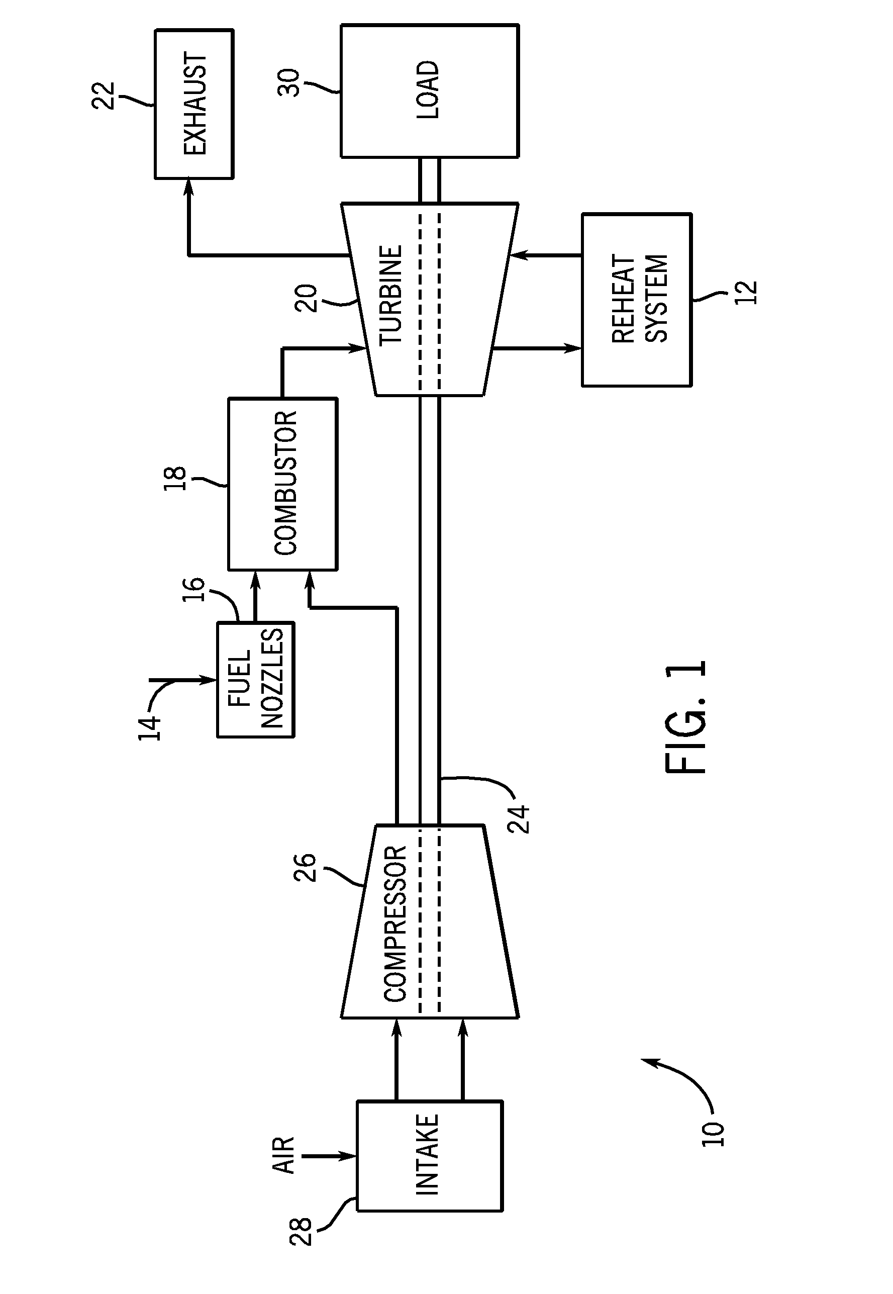
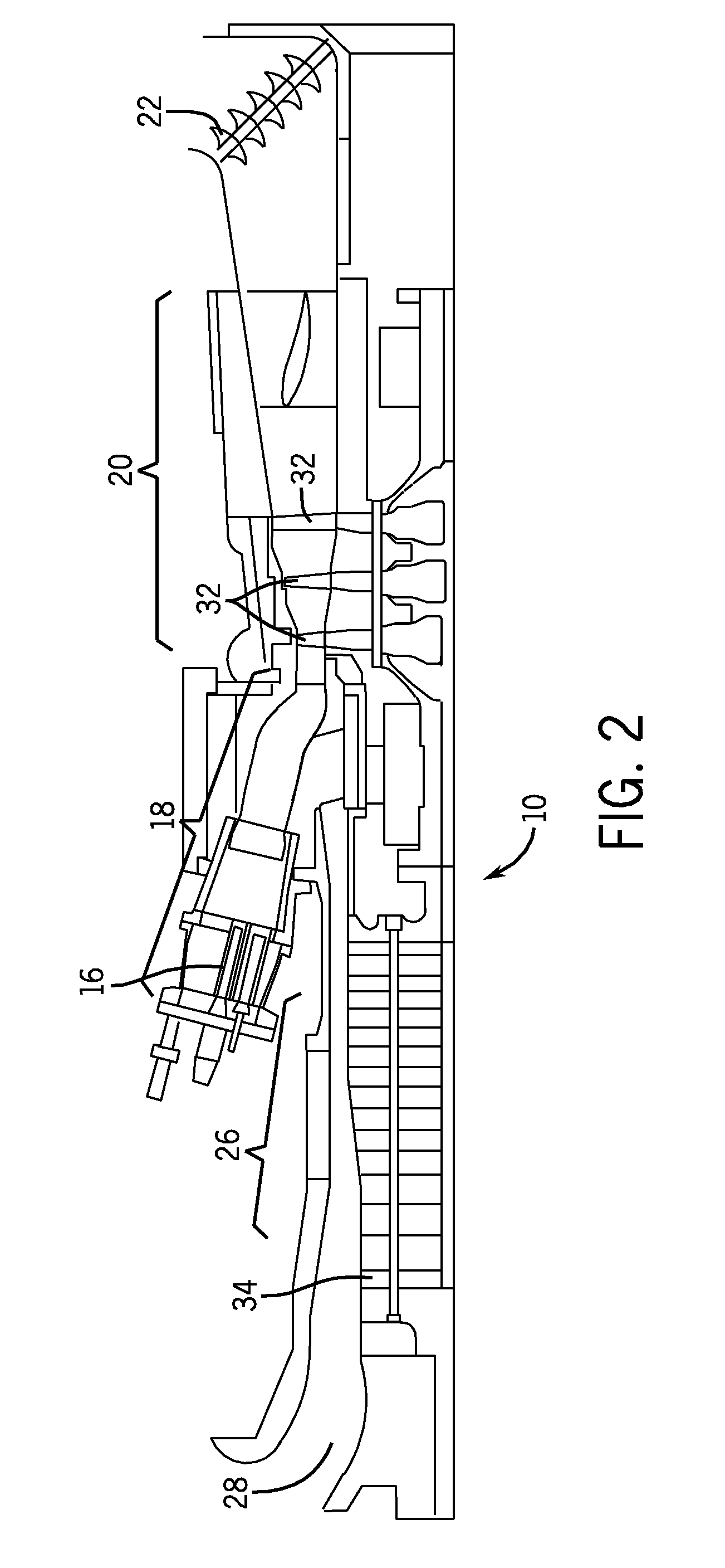
In certain exemplary embodiments, a system includes an annular duct having an inner annular wall and an outer annular wall. The system also includes a plurality of injector vanes configured to mix air and fuel to produce an air-fuel mixture, and configured to inject the air-fuel mixture into a central chamber between the inner and outer annular walls.

Description

CROSS-REFERENCE TO RELATED APPLICATION[0001]This application claims priority to and the benefit of Russian Patent Application No. 2010126341, entitled “GAS TURBINE SYSTEM HAVING PREMIXED INJECTOR VANES,” filed Jun. 29, 2010, which is herein incorporated by reference in its entirety.BACKGROUND OF THE INVENTION[0002]The subject matter disclosed herein relates to gas turbines and, more specifically, to the reheating of gas turbine gases using an annular reheat combustion system with premixed injector vanes.[0003]Gas turbine systems often have multiple turbine sections. For example, gases from one turbine section may be directed into subsequent turbine sections, with each turbine section contributing to the work performed by the gas turbine system. Unfortunately, as the gases move from one turbine section to the next, the pressure and temperature of the gases decrease as each turbine section extracts work from the flow, generally reducing the work output of each successive turbine secti...

Claims


Application Information

Patent Timeline
IPC IPC(8): F02C7/22
CPCF02C7/22F02C9/26Y02T50/67F23R3/34F23R2900/03341F23R3/20Y02E20/16Y02T50/60
Inventor STRYAPUNIN, SERGEY ALEKSANDROVICHMCMAHAN, KEVIN WESTONMYERS, GEOFFREY DAVID
Owner GENERAL ELECTRIC CO
Learn More