Blowout preventer monitoring system and method of using same

a technology of blowout prevention and monitoring system, which is applied in the direction of sealing/packing, transportation and packaging, borehole/well accessories, etc., can solve the problem that the leakage of subsurface fluids may pose a significant environmental threa

Active Publication Date: 2012-01-05
NAT OILWELL VARCO LP
View PDF16 Cites 100 Cited by
  • Summary
  • Abstract
  • Description
  • Claims
  • Application Information

AI Technical Summary

Benefits of technology

[0011]The blowout preventer may also have an electrical indicator for detecting a position of the piston. The electrical indicator may have a magnet slidably positionable on a guide in response to a magnet on the piston passing adjacent thereto, and at least one Hall Effect sensor for detecting a position of the magnet on the guide. The electrical indicator may be an inductive resistance sensor comprising a coil disposed about the cylinder. The electrical indicator may have a top end ultrasonic sensor at a top end of the cylinder and a bottom end ultrasonic sensor at a bottom end of the cylinder for detecting the piston when adjacent thereto. The electrical indicator may have an ultrasonic limit sensor. The electrical indicator may be a laser sensor. The electrical indicator may have a capacitive displacement sensor. The electrical indicator may be a sonar sensor for emitting sonar waves and sensing the waves rebounded by the piston. The electrical indicator may have at least one proximity sensor. The electrical indicator may have a flow sensor for detecting the flow of fluid through a chamber of the cylinder as the piston passes therein.

Problems solved by technology

Leakage of subsurface fluids may pose a significant environmental threat if released from the wellbore.

Method used


Image

  • Blowout preventer monitoring system and method of using same
  • Blowout preventer monitoring system and method of using same
  • Blowout preventer monitoring system and method of using same

Examples


Embodiment Construction

[0027]The description that follows includes exemplary apparatus, methods, techniques, and instruction sequences that embody techniques of the present inventive subject matter. However, it is understood that the described embodiments may be practiced without these specific details.

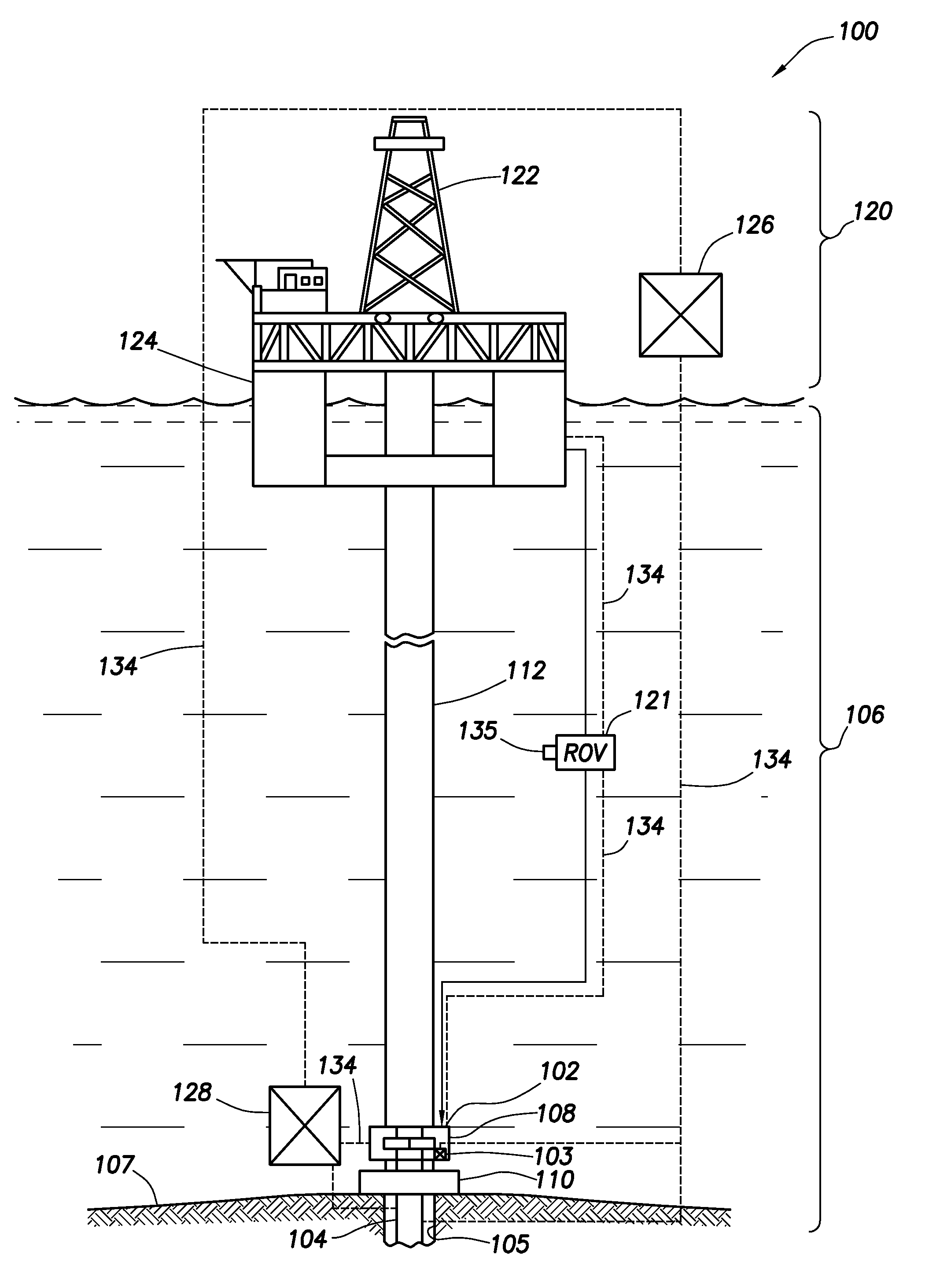
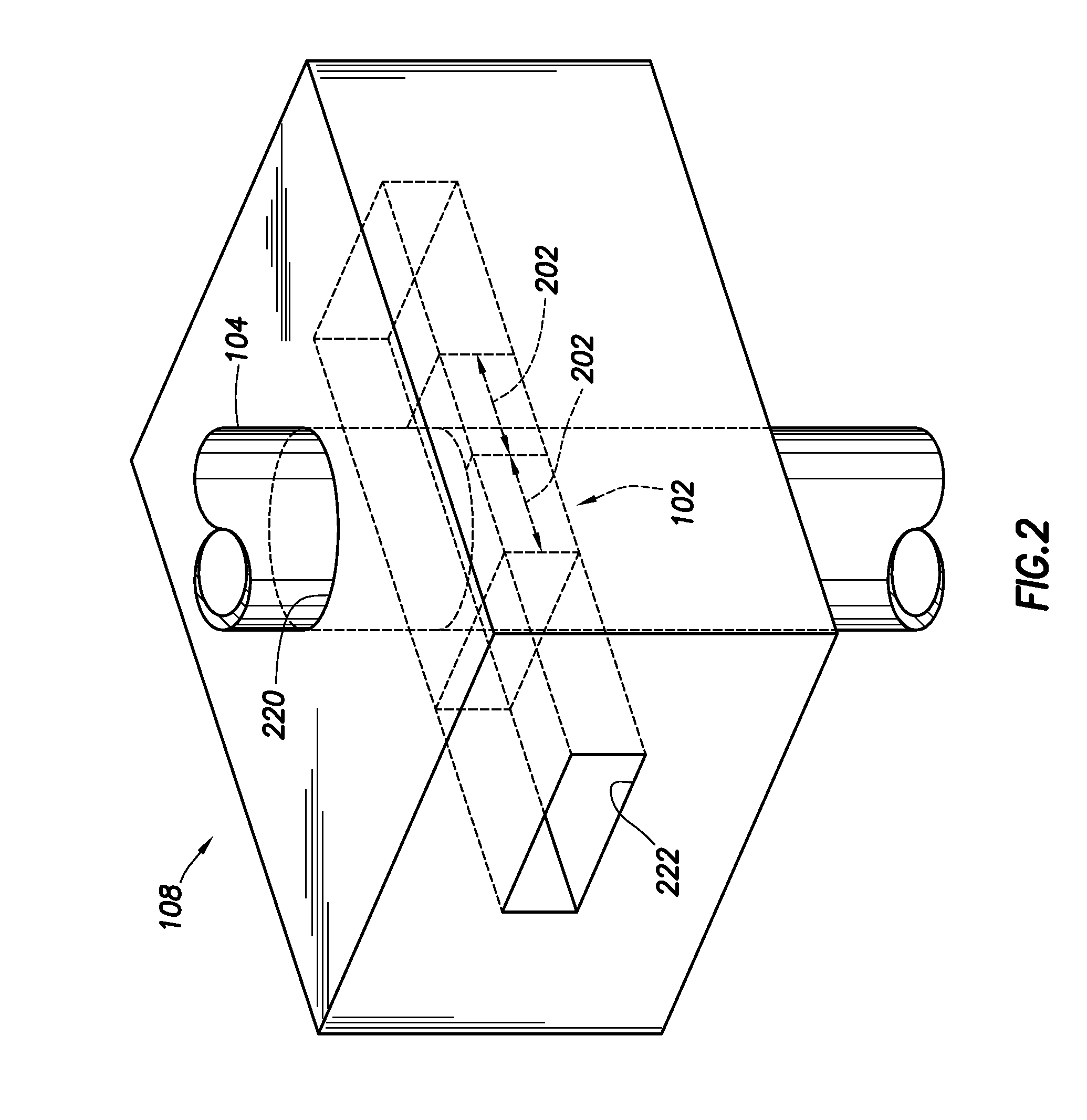
[0028]The invention is directed at techniques for providing more effective monitoring and / or measuring of the operation of the blowout preventer (BOP). The BOP may be provided with a monitor to detect, for example, a position (or location) of a ram of the BOP. These techniques may be used to provide monitoring, such as visual or electrical monitoring, of the BOP from the surface, such as while the BOP is in use on the seabed. Such monitoring techniques involve one or more of the following, among others: determination of BOP function, determination of ram position, determination of sealed position, constant monitoring of the ram position within the BOP, adaptability to wellsite equipment (e.g., various pipes...


PUM


Abstract

A blowout preventer for sealing a tubular of a wellbore is provided. The blowout preventer has a housing having a bore therethrough for receiving the tubular, at least one ram slidably positionable in the housing (each of the rams having a ram block for sealing engagement about the tubular), an actuator for selectively driving the ram block (the actuator comprising a piston slidably positionable in a cylinder), and a monitor for detecting the piston therein. The monitor has a visual indicator on an exterior of the cylinder. The visual indicator is operatively coupled to the piston for displaying a position of the piston as the piston travels within the cylinder whereby a position of the ram may be determined.

Description

CROSS-REFERENCE TO RELATED APPLICATIONS[0001]This application claims the benefit of U.S. Provisional Application No. 61 / 360,783 filed on Jul. 1, 2010, the entire contents of which are hereby incorporated by reference.BACKGROUND OF THE INVENTION[0002]1. Field of the Invention[0003]This present invention relates generally to techniques for performing wellsite operations. More specifically, the present invention relates to techniques for monitoring the operation of blowout preventers (BOPs), for example, involving determining a ram block location.[0004]2. Description of Related Art[0005]Oilfield operations are typically performed to locate and gather valuable downhole fluids. Oil rigs are positioned at wellsites and downhole tools, such as drilling tools, are deployed into the ground to reach subsurface reservoirs. Once the downhole tools form a wellbore to reach a desired reservoir, casings may be cemented into place within the wellbore, and the wellbore completed to initiate producti...

Claims


Application Information

Patent Timeline
Patent Type & Authority Applications(United States)
IPC IPC(8): E21B19/00E21B33/064E21B33/06
CPCE21B33/062E21B33/06E21B34/16Y10T137/0318Y10T137/8175Y10T137/8225Y10T137/8242Y10T137/8292
Inventor LIOTTA, JOSEPH JAMESENSLEY, ERIC TREVORJOHNSON, CHRISTOPHER DALE
Owner NAT OILWELL VARCO LP
Why Eureka
Try Eureka