
Power monitoring device for identifying state of electric appliance and power monitoring method thereof

a technology of power monitoring device and state detection, which is applied in the direction of electric devices, instruments, transportation and packaging, etc., can solve the problems of not being able to accurately detect different types of electric appliances, only monitoring the main power supply and obtaining power, and not being able to provide real-time power consumption at specific times, so as to reduce power consumption effectively and understand the cause of efficiency and power consumption

Active Publication Date: 2012-01-05
WISTRON NEWEB
View PDF13 Cites 82 Cited by
  • Summary
  • Abstract
  • Description
  • Claims
  • Application Information

AI Technical Summary

Benefits of technology

[0009]The invention is directed to a power monitoring device for identifying the state of an electric appliance based on user feedbacks and a power monitoring method therefor. The power monitoring device searches an electric appliance signature database according to variation of power consumption features to find candidate electric appliances and states of the electric appliances. Meanwhile, a user contributes data to the electric appliance signature database by confirming the search result, or selecting a correct electric appliance (or a set of correct electric appliances) from the candidate electric appliances, or providing the correct electric appliance(s) by his / her own self. A power consumption feature of the electric appliance confirmed by the user and the corresponding information are used for updating the electric appliance signature database. In other words, associations between electric appliances, states of the electric appliances, and power consumption features of the electric appliances (i.e., an electric appliance signature database) are established based on user feedbacks. Therefore, an electric appliance and the state of the electric appliance are identified according to the electric appliance signature database, and the user can understand the efficiency and power consumption cause of a currently used electric appliance in comparison with other same electric appliances or other electric appliances with the same functions. This function can be achieved by recording the power consumption of the electric appliances and comparing the power consumption features of other electric appliances. The invention helps user in drawing up a power-saving plan and reducing power consumption effectively.
[0017]As described above, in an embodiment of the invention, when the state of an electric appliance changes, a corresponding variation of the power consumption feature of the electric appliance is produced. Accordingly, associations between electric appliances, states of the electric appliances, and variations of the power consumption features of the electric appliances (i.e., an electric appliance signature database) are established with user feedbacks. Then, in an embodiment of the invention, the electric appliance signature database is searched according to a variation of a power consumption feature (for example, voltage, current, or power) of a monitored power supply, so as to identify an electric appliance and the state thereof. Thereby, a power monitoring device can record the power consumption of each electric appliance according to the variation of the state of the electric appliance, and accordingly a user can conveniently determine the power consumption cause and reduce the power consumption.
[0018]Additionally, in an embodiment of the invention, a large electric appliance signature database and a highly efficient database searching capability are provided through the Internet and the cloud computing technology such that a user can record the brand, model, power consumption cause, and power-saving suggestions of his / her electric appliances into the electric appliance signature database. Accordingly, such functions as a more specific power saving and management plan, automatic power consumption cause judgment, power consumption distribution analysis, and automatic power saving control can be achieved.

Problems solved by technology

Most electricity meters currently used by power companies are mechanical meters that can only display the total power consumption information of a house or building but cannot provide real-time power consumption at specific time or period.
Thus, the user can only monitor the main power supply and obtain the power consumption information of the main power supply but not the detailed power consumption information of each electric appliance in his / her house or building.
However, smart meter with NILM feature may not be able to correctly detect different types of electric appliances due to the difficulty in collecting the power consumption feature data for a large amount of different appliances and new models.
Besides, it is impossible to compare the power consumptions of the same electric appliance or different electric appliances having the same function in different places, houses, and building or to understand the efficiency of an electric appliance or determine the power consumption cause.
As a result, the conventional smart meter may not be able to help users to understand the power consumption situation of each electric appliance in his / her house, manage the electric appliances with high power consumptions, determine the power consumption cause, or draw up a power-saving plan effectively.
A user may not be willing to install the power monitoring system described above since the user has to install a large number of power consumption monitoring device or sensors to every electrical outlet and spend cost and effort for the installation.

Method used


Image

  • Power monitoring device for identifying state of electric appliance and power monitoring method thereof
  • Power monitoring device for identifying state of electric appliance and power monitoring method thereof
  • Power monitoring device for identifying state of electric appliance and power monitoring method thereof

Examples


first embodiment

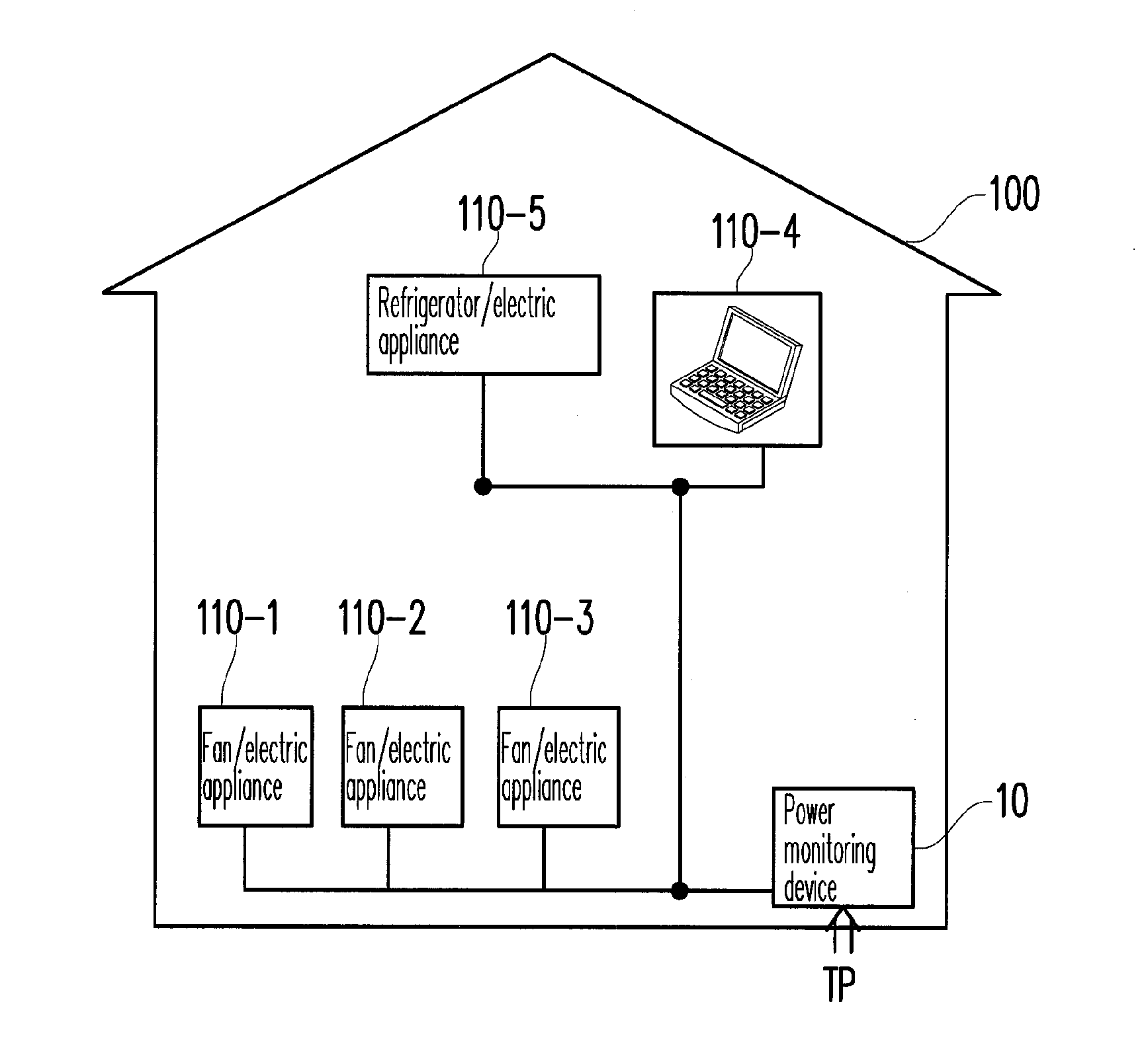
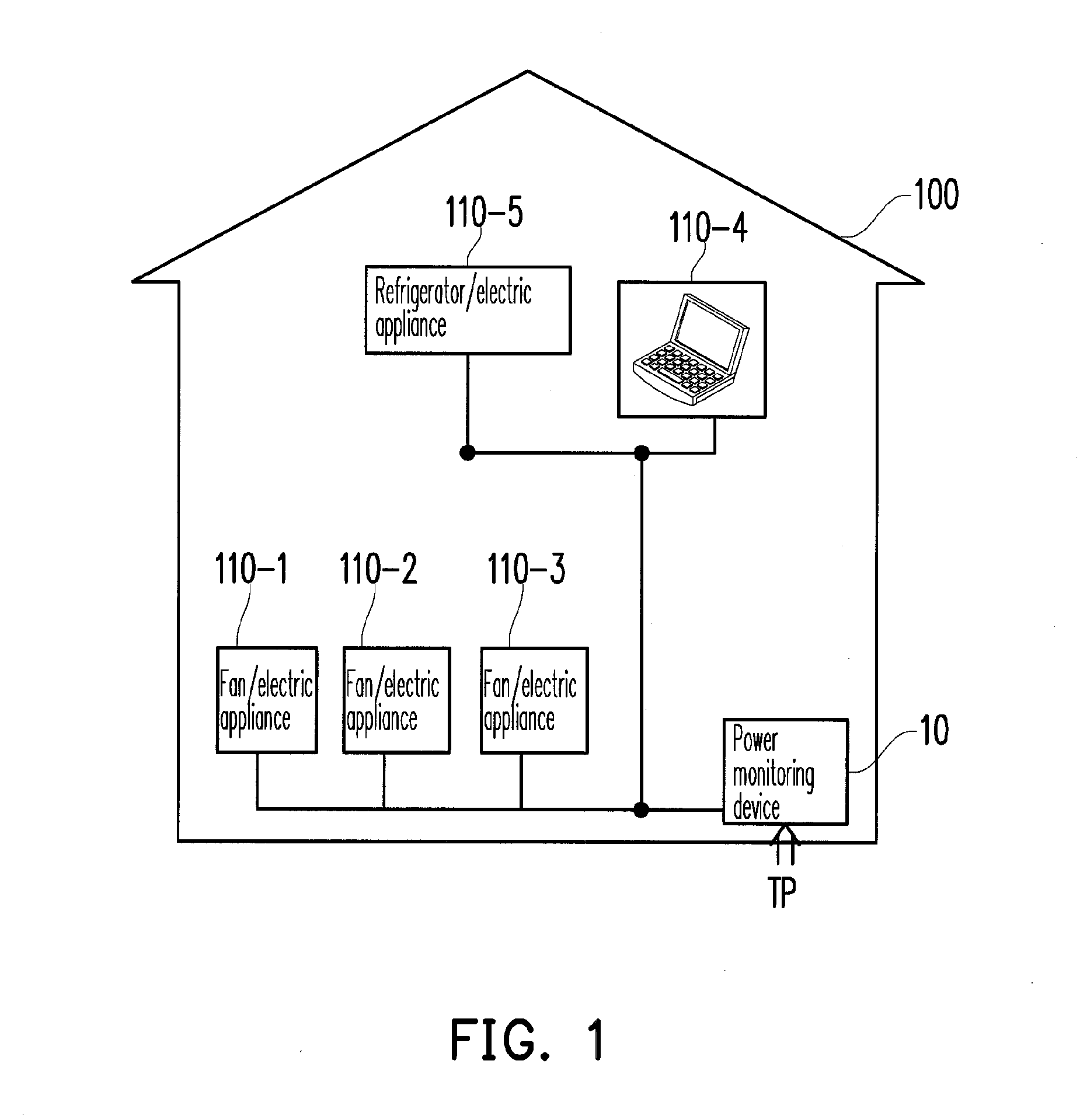
[0039]FIG. 1 is a diagram of a power monitoring device 10 for identifying the state of an electric appliance based on user feedbacks according to the invention. In the present embodiment, a household AC main power supply TP is monitored. However, the invention is not limited thereto, and in other embodiments, the power monitoring device 10 may be adopted by an enterprise or a power company for power supply management or used for monitoring any power supply. Referring to FIG. 1, there is a plurality of electric appliances 110-1-110-N in a building 100, wherein N is a positive integer greater than 1. For the convenience of description, in the present embodiment, N is set to 5, and the power monitoring device 10 can monitor at most 30 to 50 electric appliances or an AC of about 100 amp. However, the invention is not limited thereto. The main power supply TP supplies electric power to the electric appliances 110-1-110-5.

[0040]In the present embodiment, the power monitoring device 10 obt...

second embodiment

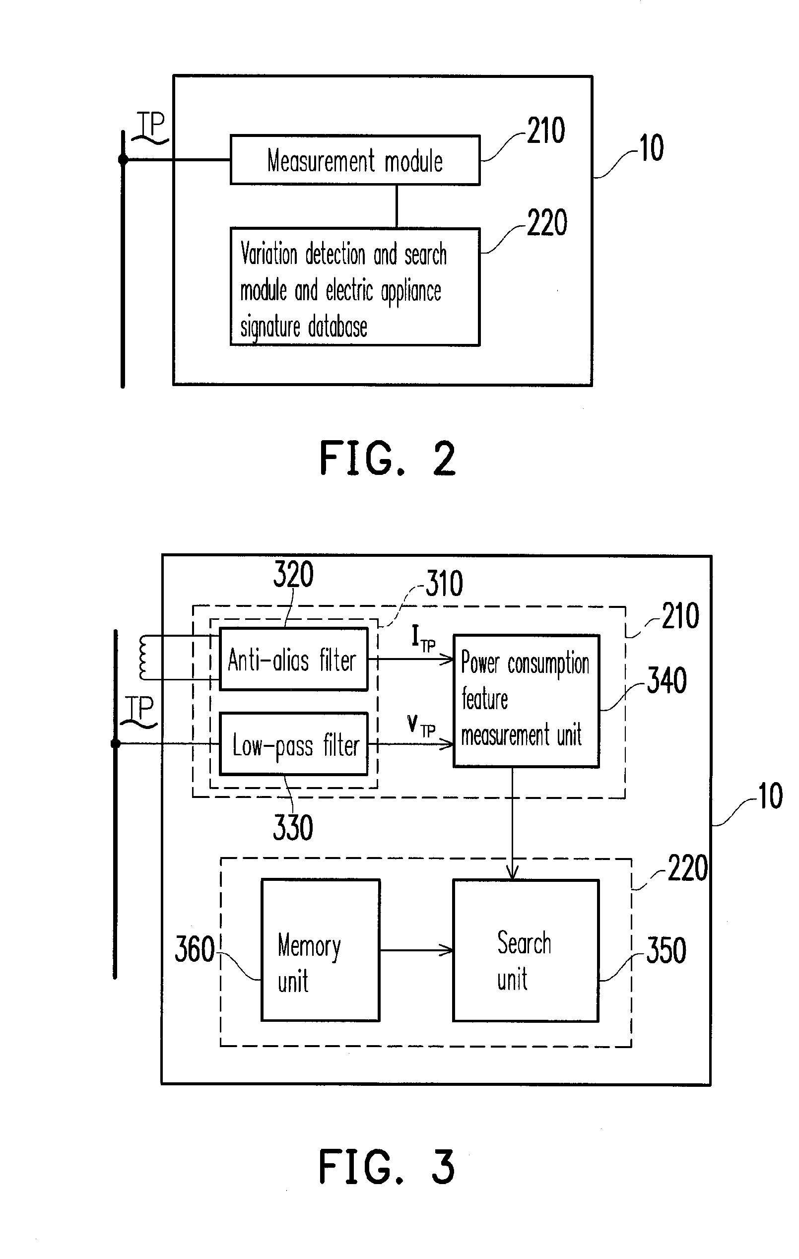
[0065]FIG. 7 is a block diagram of the power monitoring device 60 according to the invention. The power monitoring device 60 includes a measurement module 210, a variation detection unit 710, a transmission interface unit 720, and a search module 630 connected via the Internet 620. In the present embodiment, the variation detection unit 710, the transmission interface unit 720, and the search module 630 are referred in general as a variation detection and search module and electric appliance signature database 220. The variation detection unit 710 detects and calculates a variation characteristic parameter list of a variation of a power consumption feature according to a current characteristic parameter list and a previous characteristic parameter list. In the present embodiment, the power monitoring device 60 realizes its operation of searching the electric appliance signature database through the cloud computing technology in order to reduce the operation load thereof. Thus, when ...

third embodiment

[0070]FIG. 8 is a diagram of a power monitoring system 800 for identifying the state of an electric appliance according to the invention. Referring to FIG. 8, the power monitoring system 800 includes a plurality of power monitoring devices 80-1-80-5 and a plurality of electric appliance groups G1-G5. In the present embodiment, the number of the electric appliances 110 in each of the electric appliance groups G1-G5 and the total power consumption thereof are both under specific limitations. The upper limit of the electric appliance number is determined according to the maximum number of electric appliances to be monitored by the power monitoring devices 80-1-80-5. However, the invention is not limited thereto. It should be noted herein that FIG. 8 illustrates only an exemplary embodiment, and one applying the present embodiment should be able to adjust the numbers and relative positions of the power monitoring devices 80-1-80-5 and the electric appliance groups G1-G5 according to the...


PUM


Abstract

A power monitoring device for identifying the state of an electric appliance based on user feedbacks and a power monitoring method thereof are provided. The power monitoring device includes a measurement module, a variation detection and search module, and an electric appliance signature database established based on user feedbacks. When the measurement module detects a variation of a power consumption feature, the variation detection and search module searches the electric appliance signature database according to the variation to obtain electric appliances similar to the variation and the states thereof. A user contributes data to the electric appliance signature database by confirming the search result, or selecting the correct electric appliance and the state thereof. When the user confirms the search result, the power monitoring device establishes an association between the electric appliance and its electric appliance signatures and updates the electric appliance signature database.

Description

CROSS-REFERENCE TO RELATED APPLICATION[0001]This application claims the priority benefit of Taiwan application serial no. 99121853, filed on Jul. 2, 2010. The entirety of the above-mentioned patent application is hereby incorporated by reference herein and made a part of this specification.BACKGROUND OF THE INVENTION[0002]1. Field of the Invention[0003]The invention generally relates to a power measurement and monitoring technique, and more particularly, to a power monitoring technique for identifying the state of an electric appliance based on the feedbacks from users, such that the user can understand the power consumption of individual appliances conveniently.[0004]2. Description of Related Art[0005]Power monitoring devices (also referred to as electricity meters) are devices used for measuring and monitoring power consumptions of residential and industrial areas or electric appliances. A power company can sell electric power based on the power consumption information shown on an...

Claims


Application Information

Patent Timeline
IPC IPC(8): G01R21/06G06F19/00
CPCG01R19/2513G01D2204/24G01R22/06Y04S20/30
Inventor TSAO, SHIAO-LILAI, YI-SHENGLIN, MING-CHUNCHEN, YUNG-CHI
Owner WISTRON NEWEB
Learn More