

Low row steam generator inspection probe
a technology of steam generators and inspection probes, applied in the field of internal inspection probes, can solve the problem of inability to carry out further inspection, and achieve the effect of reducing resistance to movemen
- Summary
- Abstract
- Description
- Claims
- Application Information
AI Technical Summary
Benefits of technology
Problems solved by technology
Method used
Image

Examples
Embodiment Construction
[0017]Illustrative embodiments that incorporate one or more aspects of the invention are described and illustrated in the drawings. These illustrated examples are not intended to be overall limitations on the invention. For example, one or more aspects of the invention can be utilized in other embodiments and even other types of devices. Moreover, certain terminology is used herein for convenience only and is not to be taken as a limitation on the invention. Still further, in the drawings, the same reference numerals are employed for designating the same elements.
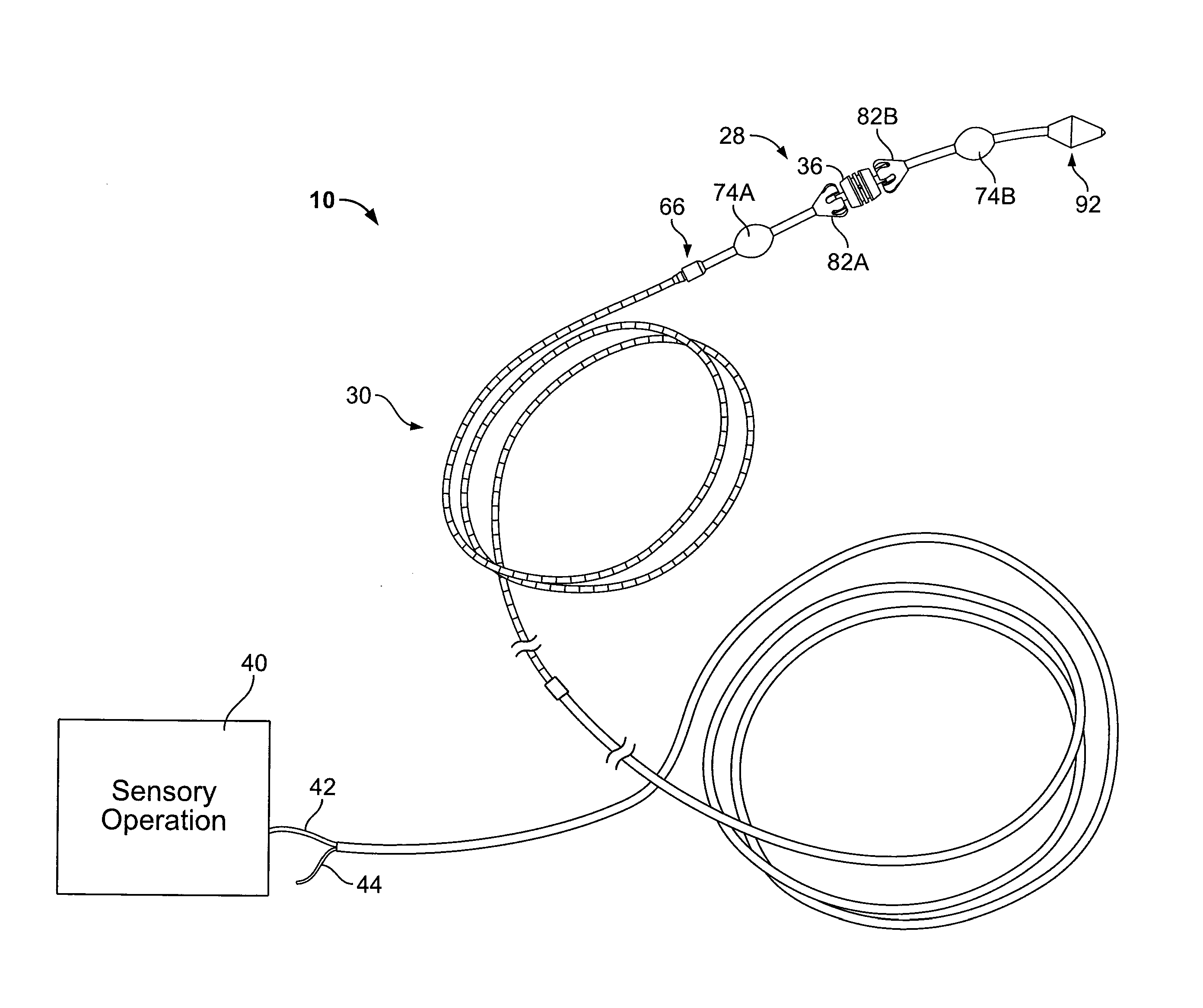
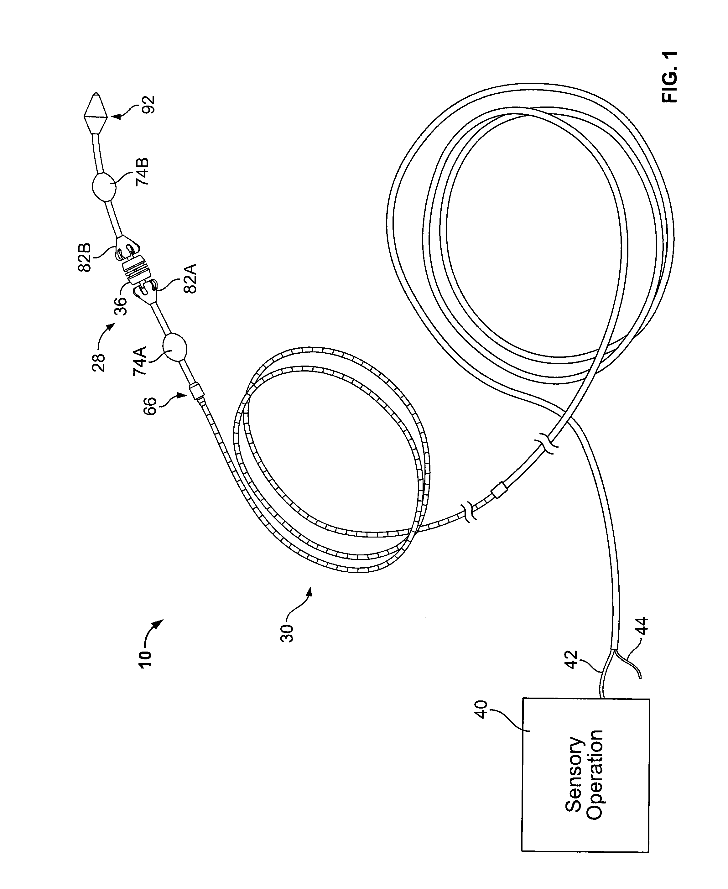
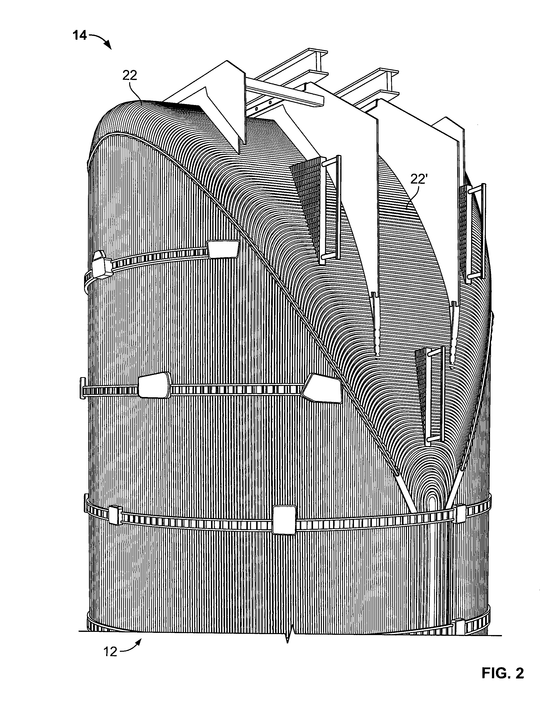
[0018]An example of an inspection assembly 10 in accordance with aspects of the present invention is schematically shown in FIG. 1. It is to be appreciated that the example is for illustrative purposes only and need not present specific limitations upon the scope of the present invention. The inspection assembly 10 is for insertion inspection of an elongate tubular member 12 (see for example, a tubular member shown within F...
PUM
 Abstract
Description
Claims
Application Information