
Adapter Configuration for a Wind Tower Lattice Structure

a technology of adapter configuration and wind turbine tower, which is applied in the direction of wind turbines, mechanical equipment, machines/engines, etc., can solve the problems of cost of tubular towers, economic disadvantage of tubular towers, and complex load transfer issues from machine head to vertical legs of lattice towers

Inactive Publication Date: 2012-02-02
GENERAL ELECTRIC CO
View PDF26 Cites 28 Cited by
  • Summary
  • Abstract
  • Description
  • Claims
  • Application Information

AI Technical Summary

Problems solved by technology

With the rising costs of these materials, the tubular towers become economically disadvantageous for certain hub heights and geographic regions.
The load transfer issues from the machine head to the vertical legs of the lattice tower can be quite complex.
This steel adapter is, however, expensive to produce and requires skilled technicians (including welders) to configure the adapter to the tower, all of which adds to the overall cost of the wind turbine.

Method used


Image

  • Adapter Configuration for a Wind Tower Lattice Structure
  • Adapter Configuration for a Wind Tower Lattice Structure
  • Adapter Configuration for a Wind Tower Lattice Structure

Examples


Embodiment Construction

[0023]Reference now will be made in detail to embodiments of the invention, one or more examples of which are illustrated in the drawings. Each example is provided by way of explanation of the invention, not limitation of the invention. In fact, it will be apparent to those skilled in the art that various modifications and variations can be made in the present invention without departing from the scope or spirit of the invention. For instance, features illustrated or described as part of one embodiment can be used with another embodiment to yield a still further embodiment. Thus, it is intended that the present invention covers such modifications and variations as come within the scope of the appended claims and their equivalents.

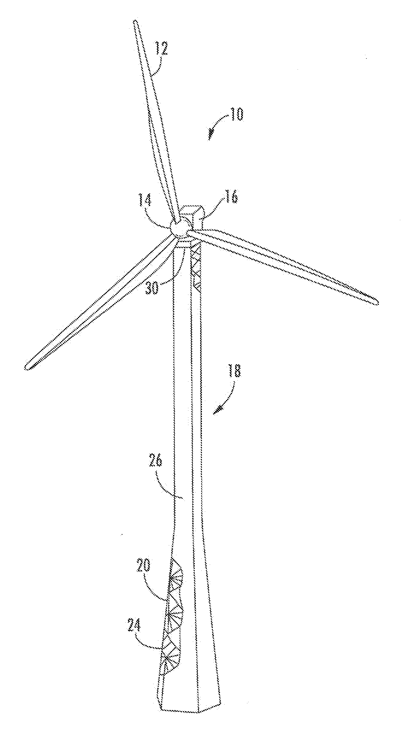
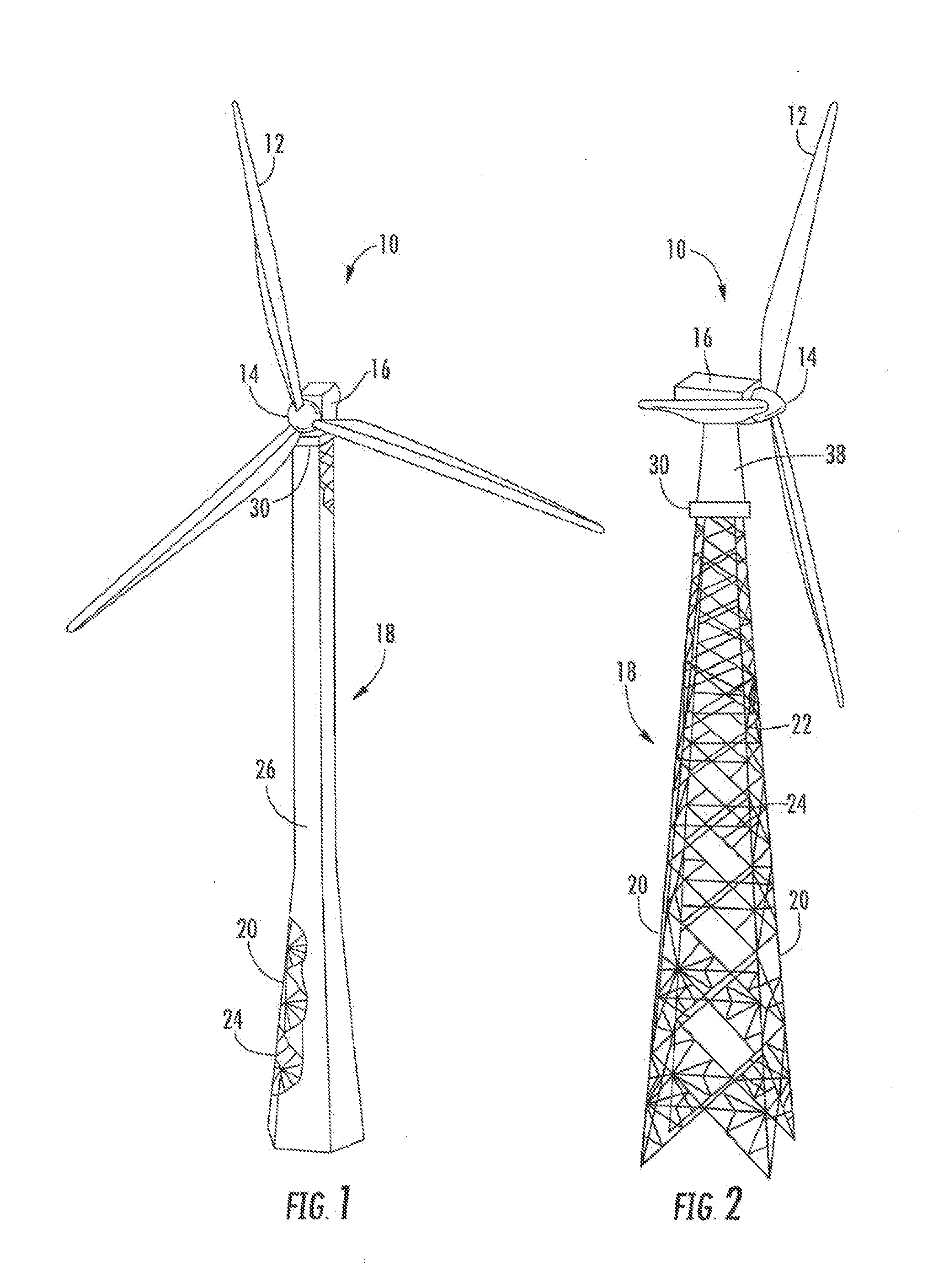
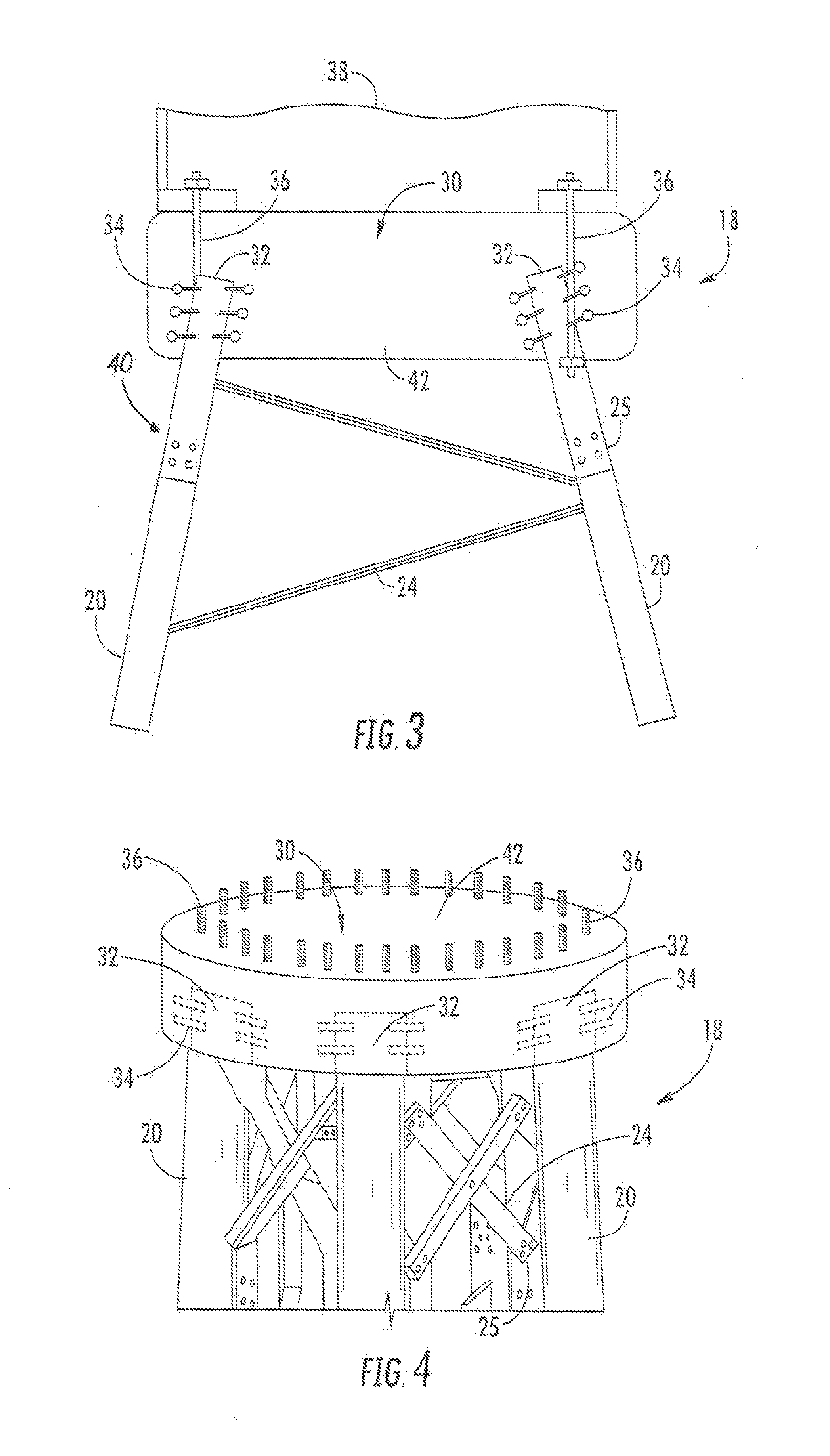
[0024]FIGS. 1 and 2 are perspective views of exemplary wind turbines 10 that may be configured in accordance with aspects of the invention. Although these wind turbines 10 are depicted as land-based structures, it should be appreciated that the invention is...


PUM


Abstract

A wind turbine tower includes a lattice tower structure having a plurality of vertically oriented columns and cross-brace members. An adapter is molded onto a top of the lattice tower structure such that top portions of the columns are embedded into the adapter. The adapter may be a concrete member molded onto the lattice tower structure.

Description

FIELD OF THE INVENTION[0001]The present invention relates generally to wind turbine tower structures, and more particularly to an adapter configuration that may utilized between the lattice tower and an upper tubular component of the wind turbine, or at the interface between a jacket foundation and tower for offshore wind turbines.BACKGROUND OF THE INVENTION[0002]Conventional wind turbine towers typically include a tubularpole construction to support a wind turbine at a considerable height to capture wind energy. The tubular tower configuration is relatively simple and easier to assemble, but utilizes a considerable amount of material, particularly steel. With the rising costs of these materials, the tubular towers become economically disadvantageous for certain hub heights and geographic regions.[0003]The growing acceptance of wind energy as a significant alternative energy source depends on large part in maintaining the cost-per-kilowatt of power produced at an acceptable level. I...

Claims


Application Information

Patent Timeline
Patent Type & Authority Applications(United States)
IPC IPC(8): E04H12/00
CPCE04H2012/006Y02E10/728F05B2240/9121F03D11/04F03D13/20Y02E10/72
Inventor VOSS, STEFAN
Owner GENERAL ELECTRIC CO
Learn More