Apparatus and Method for Defining a Safety Zone for a Vehicle

a technology for safety zones and vehicles, applied in vehicle components, alarms, instruments, etc., can solve problems such as difficulty for operators in judging the size of their own or other vehicles, increased accidents risk, and differences in speed

Inactive Publication Date: 2012-02-02
TOLL GORDON
View PDF2 Cites 43 Cited by
  • Summary
  • Abstract
  • Description
  • Claims
  • Application Information

AI Technical Summary

Benefits of technology

[0012]An object of the present invention is to provide an apparatus, use of an apparatus and method for defining a safety zone for a vehicle. In accordance with an aspect of the present invention, there is provided an apparatus for defining a safety zone for a vehicle, the apparatus comprising one or more radiation sources operatively coupled to the vehicle, the one or more radiation sources configured to create one or more visible identifiers at one or more locations, the locations defining a pre-determined position relative to the vehicle, and the one or more visible identifiers thereby defining the safety zone for the vehicle.
[0013]In accordance with another aspect of the present invention, there is pro

Problems solved by technology

As such, the risk of accidents has increased considerably.
In addition, this wide variety of different types of vehicles has also led to different risk factors.
These factors include differences in speed, visibility to others, capability of seeing others because of different vantage points and/or fewer windows and mirrors, and difficulties for operators in judging the size of their own or other vehicles.
There are many reasons that cause and exacerbate accidents, including, for example, the operator of a vehicle may not see another vehicle until it is too late to avoid the accident.
Other reasons may result from the fact that some vehicles often present a much lower profile which is not able to be seen over features of larger vehicles or obstacles.
In addition, there is often a significant difference in the rate of travel between different vehicles, people and animals that may exacerbate this problem.
For example, a passing automobile may not have a chance to identify a cyclist until the last moment when it may be too late to take action to avoid a collision.
Another related cause of such accidents is the lack of adequate lighting systems on vehicles.
While the after-market provides many types of battery or generator powered lights for people, animals and vehicles, such lights often fail to be seen until too late and often do little to adequately indicate position or a safe distance from the person, vehicle, or animal that must be maintained.

Method used


Image

  • Apparatus and Method for Defining a Safety Zone for a Vehicle
  • Apparatus and Method for Defining a Safety Zone for a Vehicle
  • Apparatus and Method for Defining a Safety Zone for a Vehicle

Examples


example 1

Visible Radiation Source with Polygonal Scanner

[0094]FIG. 3 shows a conceptual illustration of a vehicle having associated therewith an apparatus in accordance with an embodiment wherein visible identifiers are at pre-determined positions in pre-determined geometries. FIG. 3 shows a representation of an apparatus in accordance with one embodiment mounted on a vehicle 340 (which may be a bicycle, car, motorcycle, person, animal, or other vehicle) comprising the use of polygonal scanners 320 to direct beams of visible radiation from a source of visible radiation 330 such that they create a highly visible reflection covering an area in front of the vehicle 310 and to the side of the vehicle 315. This configuration of visible identifiers can ensure that the vehicle 340 is both visible to other vehicles sharing the same surface, but also provides an increased periphery for other vehicles to move around, thereby increasing the space between the vehicle 340 in question and others.

[0095]Thi...

example 2

Multiple Visible Radiation Sources

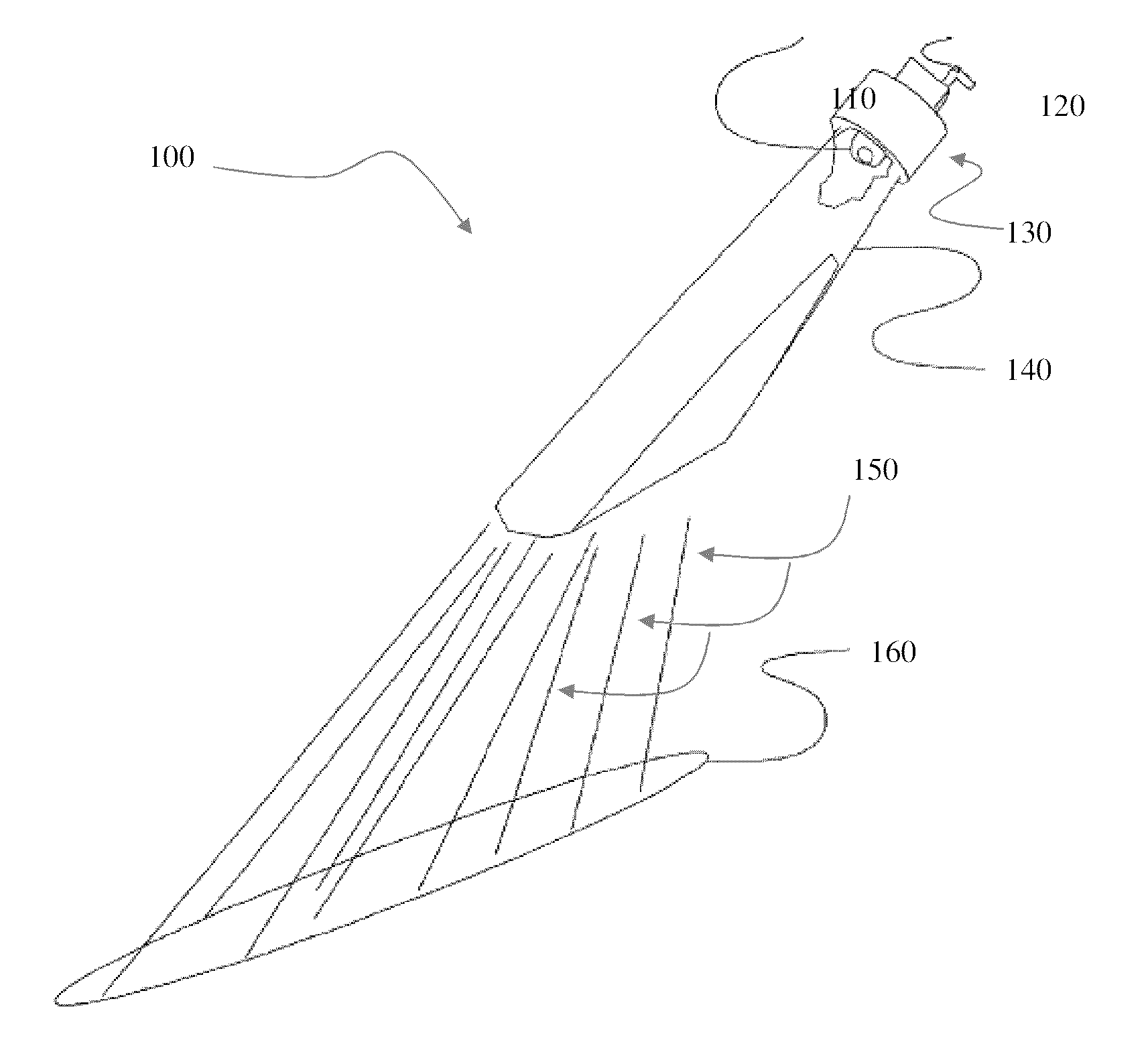
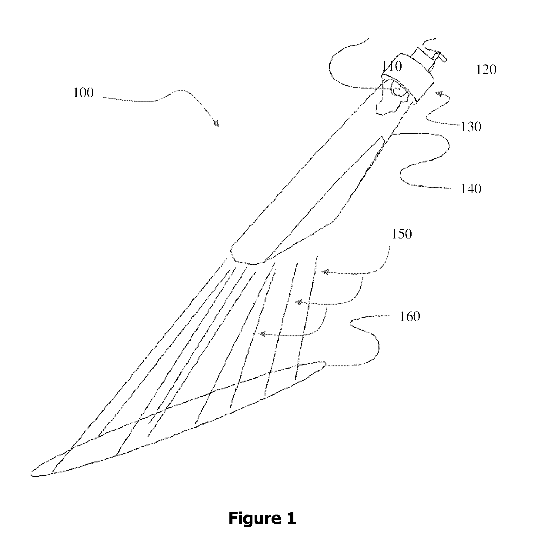
[0115]FIG. 4 provides an additional conceptual illustration of a vehicle having mounted thereon an embodiment of the apparatus with visible identifiers directed to pre-determined positions in pre-determined geometries. The apparatus comprises a plurality of lasers 100 directing beams of radiation 150 towards the surface proximal to the vehicle 420. The visible identifiers 410 in this example could be representative of either point reflections on the surface of travel or laser-induced breakdown of air above said surface. The vehicle 420 may be representative of a bicycle, car, motorcycle, person, animal, or other vehicle.

[0116]This embodiment uses radiation sources 100 that comprises a number of components, including green lasers, energy generator from a battery, casing and a levelling switch. The components can be configured to operate according to the following specifications:[0117]Green Laser:[0118]Class IIIb,[0119]wavelength—532 nm,[0120]output—>...

example 3

Laser-Induced Breakdown of Air

[0135]FIG. 5 shows an exemplary apparatus for inducing the breakdown of air 500 using a laser. The beam of radiation is not within the visible spectrum of light. The breakdown of air 510 is occurring at a pre-determined position. One or more radiation sources, such as the one in FIG. 5, can be used in embodiments of the apparatus, methods and uses disclosed herein in order to create a visible identifier at one or more pre-determined position proximate to a vehicle.


PUM


Abstract

An apparatus for defining a safety zone for a vehicle, the apparatus comprising one or more radiation sources operatively coupled to the vehicle, the one or more radiation sources configured to create one or more visible identifiers at one or more locations, said locations defining a pre-determined position relative to the vehicle, and said one or more visible identifiers thereby defining the safety zone for the vehicle. There is also disclosed, the use of one or more vehicle-mounted radiation sources to direct radiation to one or more pre-determined positions to create a conspicuous safety zone proximal to a vehicle. There is further described, a method for creating a safety zone proximal to a vehicle, comprising the steps of mounting one or more radiation sources on the vehicle; directing said one or more radiation sources towards one or more pre-determined positions proximal to the vehicle; and configuring the one or more radiation sources to create one or more conspicuous visible identifiers at the one or more pre-determined positions to define a safety zone for the vehicle.

Description

FIELD OF THE INVENTION[0001]The present invention pertains to an apparatus and method for defining a safety zone for a vehicle.BACKGROUND[0002]Vehicles are increasingly being used by individuals and organizations for a wide variety of reasons. In addition to the increase in the number and types of vehicles being used, the number of shared spaces and travelways has also increased, both because of said increase in numbers and because travelways which were originally intended for certain types of vehicles are now being used by people and / or many different vehicle types. Further, people, animals and vehicles that share such spaces have many different attributes including conspicuousness, visibility to others, rate of travel, vantage point, profile, size and weight, to name a very few.[0003]For example, an increasing number of vehicles, including bicycles, motorcycles, cars, trailers, strollers, trucks, buses, trolleys, and other vehicles are being used on roads or other spaces which wer...

Claims


Application Information

Patent Timeline
IPC IPC(8): B60Q1/26
CPCB60Q2400/50B60Q1/50
Inventor TOLL, GORDON
Owner TOLL GORDON
Why Eureka
Try Eureka