Antenna Device Whose Vertical and Horizontal Positions can be adjusted

a technology of antenna box and vertical position, which is applied in the direction of antenna, antenna details, electrical equipment, etc., can solve the problems of inability to accurately and clearly receive television signals, the angle of the conventional antenna device cannot be easily adjusted, etc., and achieve the effect of easy and quick adjustment of the position of the antenna box

Inactive Publication Date: 2012-02-02
QUANYI ELECTRONICS
View PDF4 Cites 17 Cited by
  • Summary
  • Abstract
  • Description
  • Claims
  • Application Information

AI Technical Summary

Benefits of technology

[0009]According to the primary advantage of the present invention, the orientation of the antenna box is adjustable so that the antenna box can be disposed at a horizontal position or a vertical position so as to receive a wireless signal exactly and clearly.
[0010]According to another advantage of the present invention, a user only needs to insert the insertion block of the antenna box into the mounting sleeve of the fixing seat to attach the antenna box to the fixing seat so that the position of the antenna box can be adjusted easily and quickly.
[0011]According to a further advantage of the present invention, the insertion block of the antenna box is fixed in the mounting sleeve of the fixing seat so that the antenna box is combined with the fixing seat solidly and stably to prevent the antenna box from being deflected freely.
[0012]Further benefits and advantages of the present invention will become apparent after a careful reading of the detailed description with appropriate reference to the accompanying drawings.
[0013]FIG. 1 is a perspective view of an antenna device in accordance with the preferred embodiment of the present invention.
[0014]FIG. 2 is a perspective of a fixing seat of the antenna device as shown in FIG. 1.

Problems solved by technology

However, the receiving angles of the conventional antenna device cannot be adjusted easily and quickly so that the antenna cannot receive the television signals exactly and clearly.

Method used


Image

  • Antenna Device Whose Vertical and Horizontal Positions can be adjusted
  • Antenna Device Whose Vertical and Horizontal Positions can be adjusted
  • Antenna Device Whose Vertical and Horizontal Positions can be adjusted

Examples


Embodiment Construction

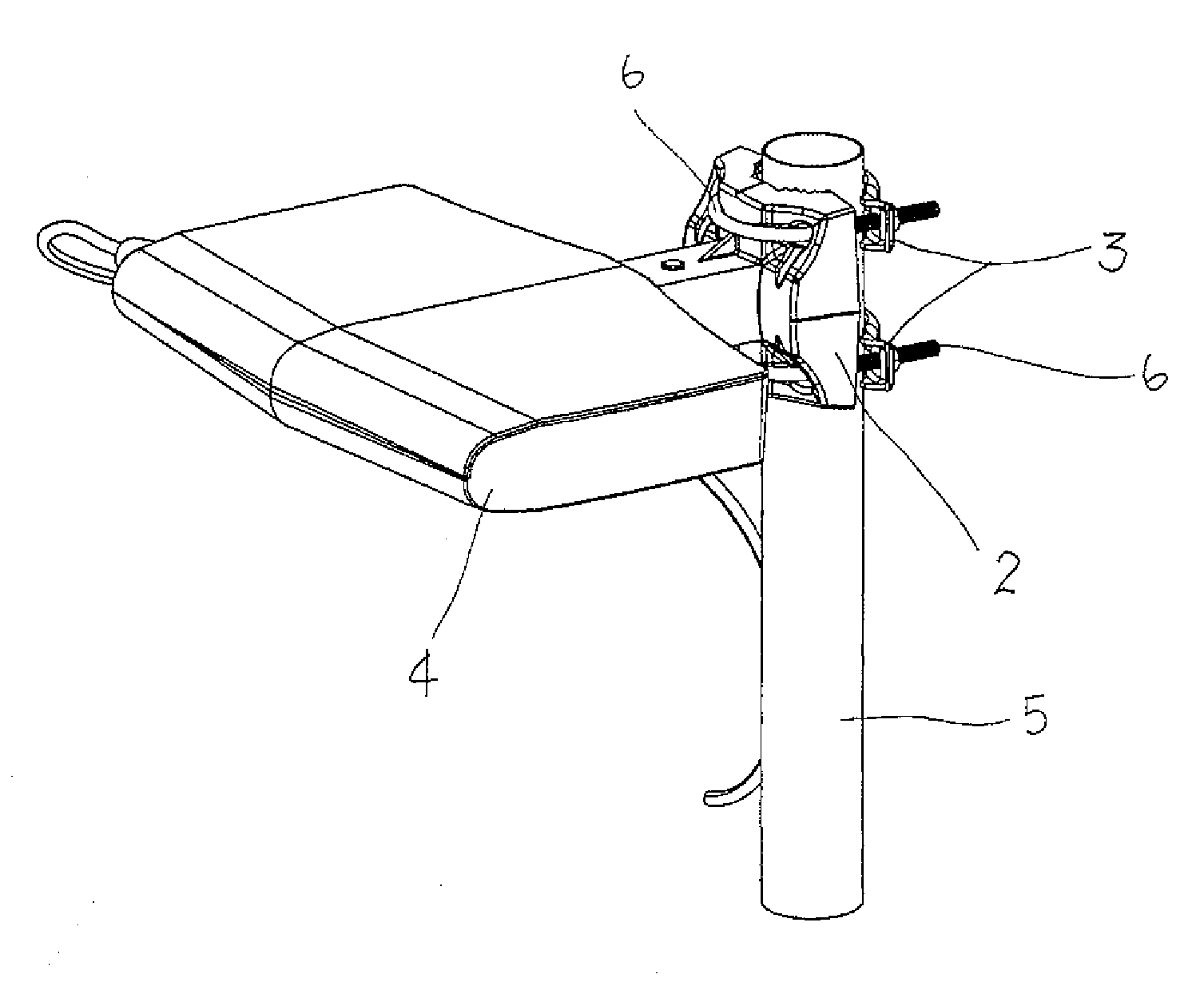
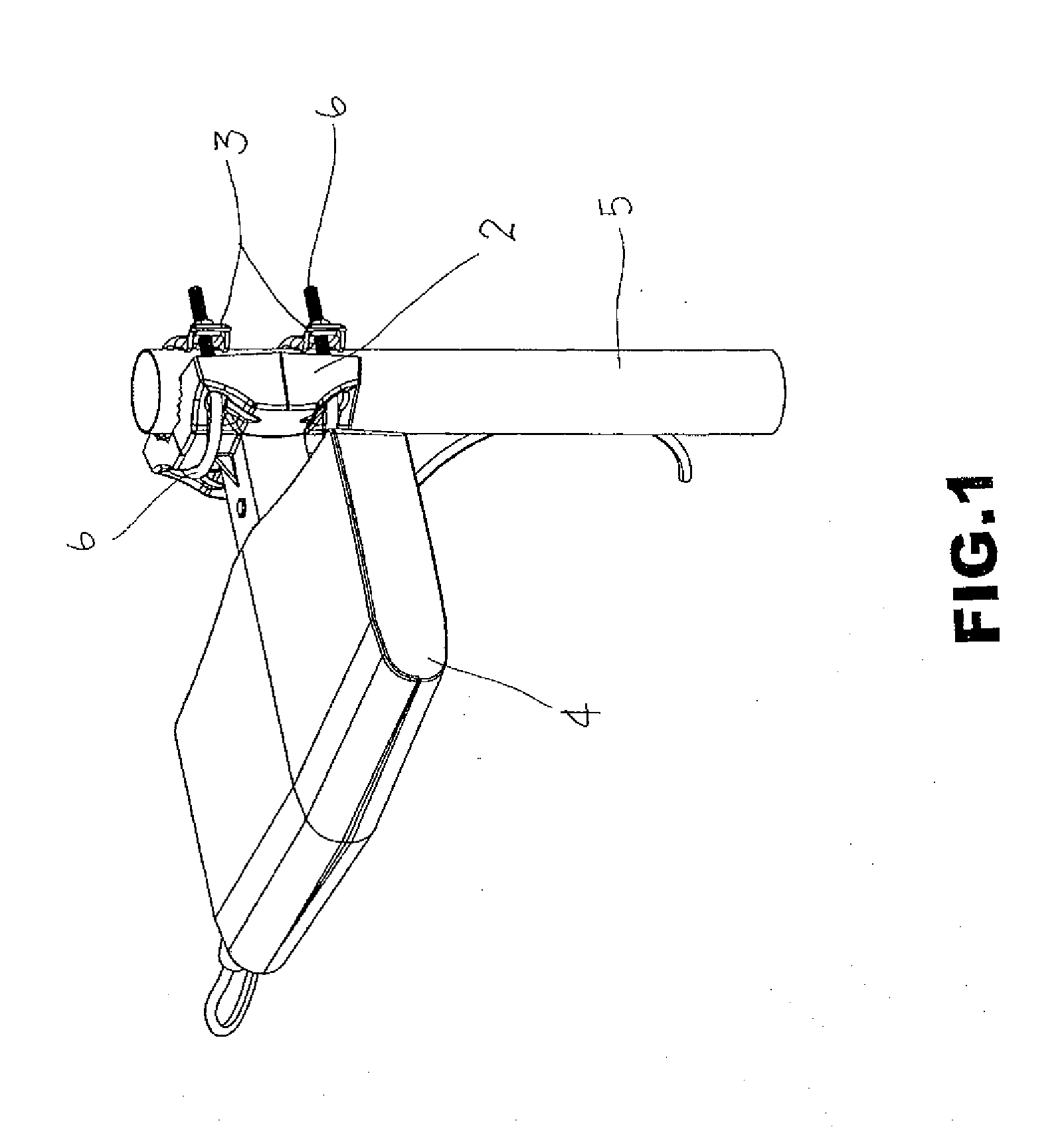
[0023]Referring to the drawings and initially to FIGS. 1-4, an antenna device in accordance with the preferred embodiment of the present invention comprises a support pole 5, a fixing seat 2 having a first end mounted on the support pole 5, at least one clamping member 3 mounted on the support pole 5 and combined with the first end of the fixing seat 2 by at least one U-shaped locking bolt 6, and an antenna box 4 mounted on a second end of the fixing seat 2.

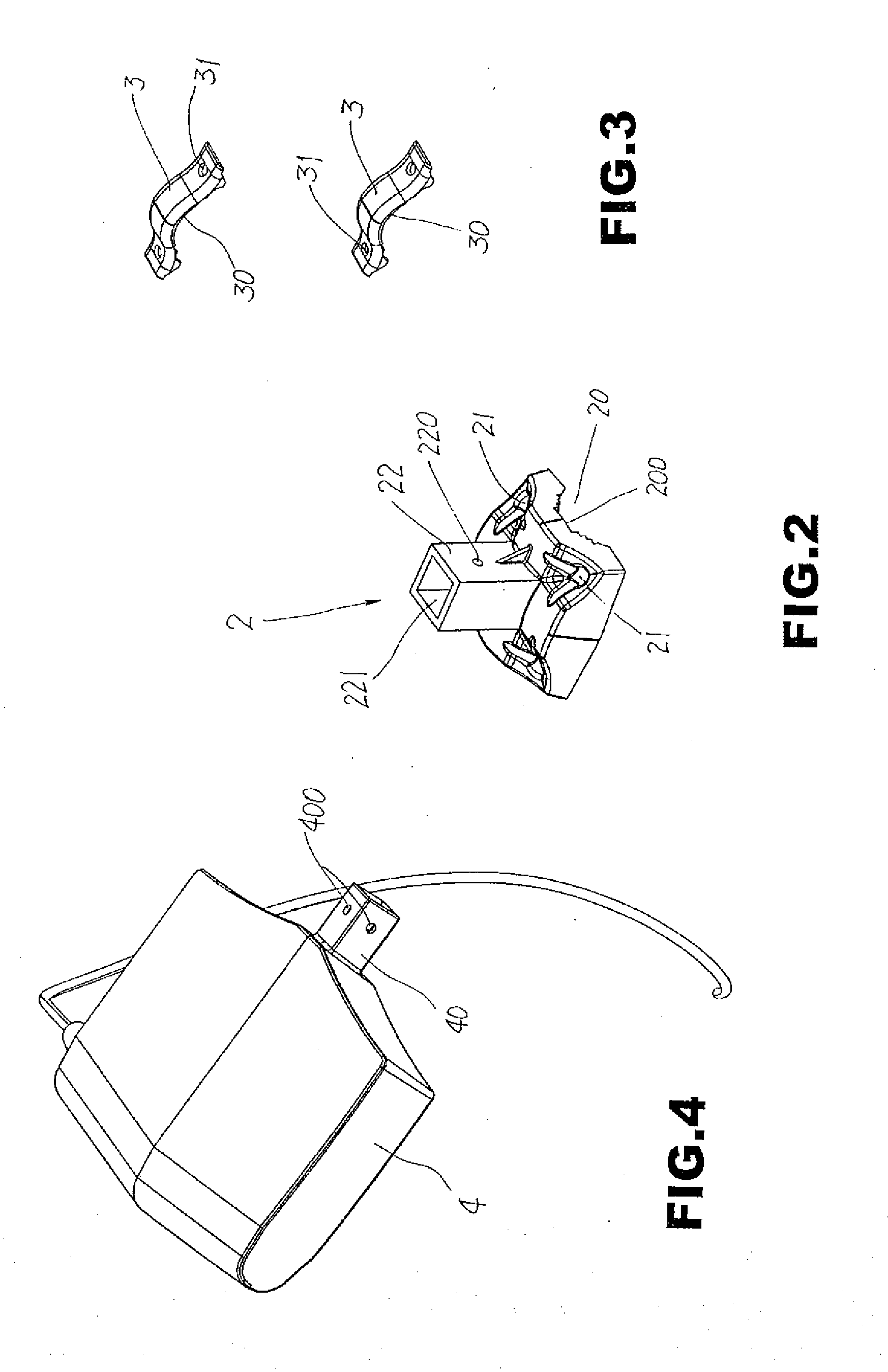
[0024]The first end of the fixing seat 2 has an end face provided with a first arc-shaped portion 20 mounted on the support pole 5. The first arc-shaped portion 20 of the fixing seat 2 is provided with a serrated face 200 engaging the support pole 5 tightly and closely. The first end of the fixing seat 2 has a peripheral wall formed with a plurality of through holes 21 to allow passage of the locking bolt 6. The second end of the fixing seat 2 is provided with a square hollow mounting sleeve 22. The mounting sleeve 22 of the fixi...


PUM


Abstract

An antenna device includes a support pole, a fixing seat mounted on the support pole, at least one clamping member mounted on the support pole and combined with the fixing seat by at least one locking bolt, and an antenna box mounted on the fixing seat. The fixing seat is provided with a square mounting sleeve which has a mounting chamber and two opposite fixing holes. The antenna box has a square insertion block inserted into the mounting chamber. The insertion block has a plurality of adjusting holes. Thus, the orientation of the antenna box is adjustable so that the antenna box can be disposed at a horizontal position or a vertical position so as to receive a wireless signal exactly and clearly.

Description

BACKGROUND OF THE INVENTION[0001]1. Field of the Invention[0002]The present invention relates to an antenna device and, more particularly, to an antenna device for receiving television signals.[0003]2. Description of the Related Art[0004]An antenna device is mounted outdoors for receiving television signals. A conventional antenna device comprises a skeleton having a fishbone, a plurality of aluminum tubes mounted on and parallel with the skeleton, an antenna box mounted on the bottom of the skeleton and connected with an antenna, and a cable connected between the antenna box and an indoor television. The conventional antenna device is mounted on an object, such as a pole and the like, which is located at higher location so as to receive the television signals clearly. However, the receiving angles of the conventional antenna device cannot be adjusted easily and quickly so that the antenna cannot receive the television signals exactly and clearly.BRIEF SUMMARY OF THE INVENTION[0005]...

Claims


Application Information

Patent Timeline
Patent Type & Authority Applications(United States)
IPC IPC(8): H01Q1/12
CPCH01Q1/125H01Q1/1228
Inventor LO, SHAN-GOW
Owner QUANYI ELECTRONICS
Why Eureka
Try Eureka