Air duct cover and boot

a technology of air ducts and boot covers, which is applied in the field of air duct covers and boot covers, can solve the problems of time-consuming and laborious to properly size the opening to accommodate the duct, difficult to properly align the duct and the opening, and other problems, so as to eliminate or diminish the disadvantages and problems

Active Publication Date: 2008-06-24
HADLOCK JR LEONARD R
View PDF42 Cites 18 Cited by
  • Summary
  • Abstract
  • Description
  • Claims
  • Application Information

AI Technical Summary

Benefits of technology

[0015]Advantageously, the flange may increase the ease and efficiency of installing the duct by acting as a guide to quickly and easily position the duct in the correct location. The flange may also allow the duct to be used in connection with openings and structures of various sizes and configurations. For example, if a section of the duct is intended to be disposed within an opening, then the flange may allow the duct to be positioned within openings of various sizes. That is, an opening need not be slowly and painstakingly sized to accommodate the duct because the flange may extend outwardly to span any gap between the body and the opening. Further, the flange may rest upon a portion of the floor, ceiling or other structure when the duct is being installed. This may facilitate installation of the duct because it may allow, for example, a person to leave that portion of the duct hanging from the supports to retrieve fasteners, adhesives and / or other suitable means used to attach the duct into the desired position. Further, with the flange resting upon the floor and / or the supports, a person may more easily operate a device (such as a nail gun, a staple gun, a hammer or other tool) used to attach the duct to the desired structure.
[0024]A further aspect is a duct that may include one or more components constructed from plastic. Advantageously, the plastic components may be relatively lightweight, which may reduce shipping costs and make the duct easier to install. Also, the plastic components may be relatively strong and / or durable. Additionally, the plastic components may be relatively weather and moisture resistant. Further, the plastic components may be quickly and easily manufactured via a molding process, such as injection molding, compression molding, rotary molding or other suitable molding process. Advantageously, any combination of the plastic components of the duct section may be integrally formed during a molding process as part of a unitary, one-piece structure. It will be understood that the components of a duct section need not be constructed using a molding process and that other manufacturing processes may be used to construct the duct section. It will be also understood that some or all of the components of a duct section may be constructed using metal, plastic, synthetics, polymers, and / or other materials having other characteristics.

Problems solved by technology

Unfortunately, when a duct is attached to an opening in a wall, a floor or a ceiling, it can be time consuming to properly size the opening to accommodate the duct.
Further, when attaching a duct to the opening, it can be difficult to properly align the duct and the opening.
After a duct is installed, other problems may occur.
Consequently, when activated, the HVAC systems may blow this debris throughout the office building or home, creating a mess and a potential health risk.
Further, the water and / or debris may promote the growth of mold, bacteria or other pathogens, which the HVAC systems may blow throughout the office building or home.
In addition, birds or other animals may enter and become trapped in the ducts.
For example, these animals may get stuck or lost within the ducts and may eventually die within the ducts.
Consequently, when activated, the HVAC systems may blow the smell of decaying animals throughout the office building or home.
In addition, the decaying animals may create a health risk in the building or home.

Method used


Image

  • Air duct cover and boot
  • Air duct cover and boot
  • Air duct cover and boot

Examples


Embodiment Construction

[0009]A need therefore exists for a duct that eliminates or diminishes the disadvantages and problems described above.

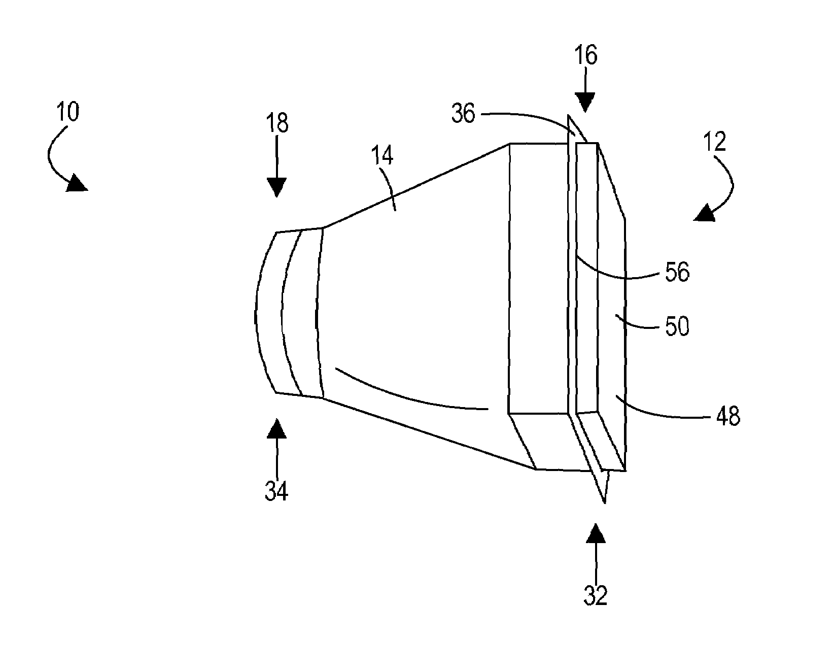
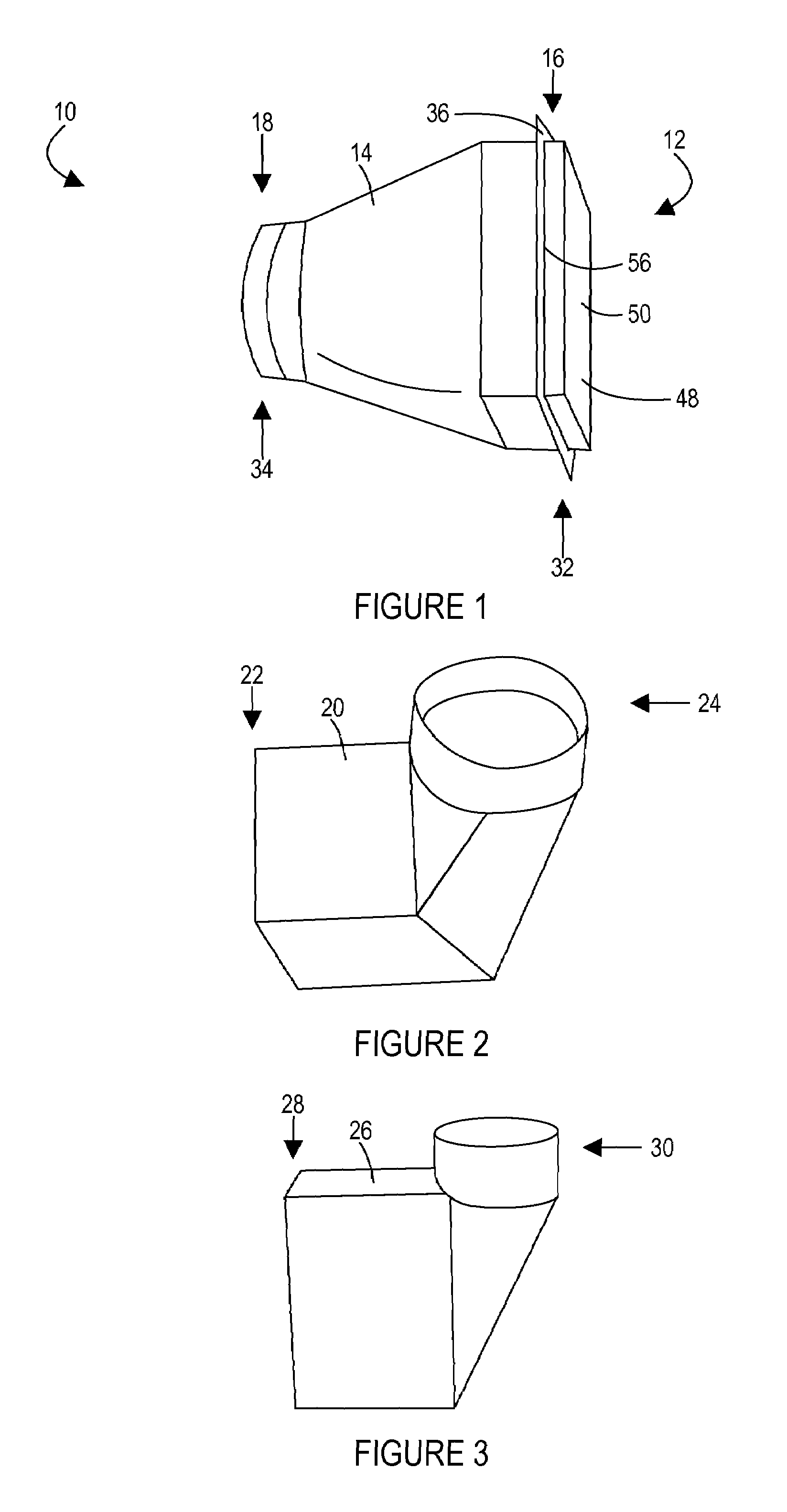
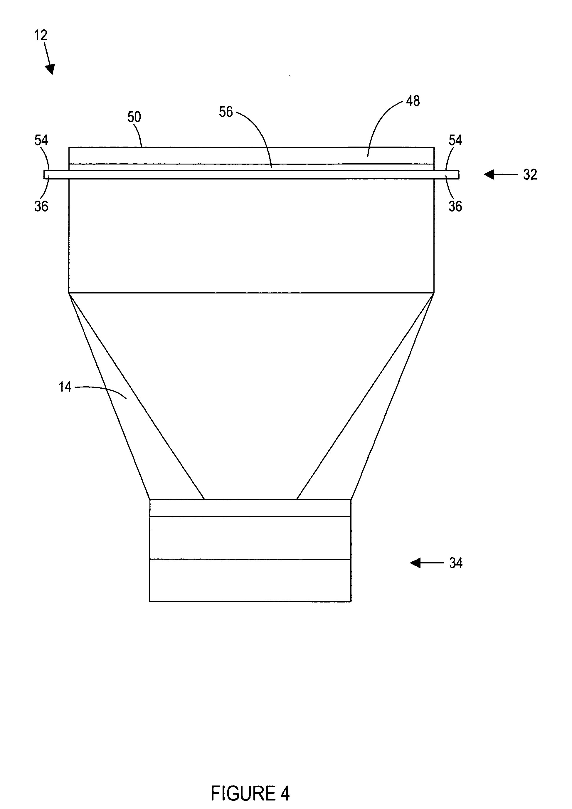
[0010]One aspect of the invention is a duct that may form part of a ventilation system. For example, the duct may be part of an HVAC or other suitable system. The duct preferably includes a hollow interior portion that allows air to be conveyed or transported through the duct. This allows the duct, for example, to be part of a ventilation system for a home, office and other suitable types of buildings and structures. The duct may also be used with other systems for conveying gases, liquids and / or other materials. In addition, the duct may form part of a housing and / or enclosure such as for wiring, cables and the like.

[0011]Another aspect is a duct that may include one or more sections. For example, the duct may be part of a network or system that provides ventilation to a building. The duct may include a boot that is sized and configured to direct ventilation into a ...


PUM


Abstract

A heating, ventilation and air conditioning (HVAC) system may include one or more ducts and each duct may include one or more sections. A duct section, for example, may include a flange, which may help increase the ease and efficiency of installing the duct section. The flange may also help provide a seal between portions of the duct section and other structures. A duct section may include a cover, which may advantageously help prevent animals, debris and the like from entering and / or passing through the duct section. A duct section may also include a barrier, which may also help prevent animals, debris and the like from entering and / or passing through the duct section. The barrier may also include one or more air-permeable portions through which at least some air may advantageously pass.

Description

CROSS-REFERENCE TO RELATED APPLICATIONS[0001]This application claims priority to and the benefit of United States provisional patent application Ser. No. 60 / 629,853, filed Nov. 18, 2004 and entitled HEATING VENT WITH DISCHARGE COVER, which is incorporated by reference herein in its entirety.BACKGROUND OF THE INVENTION[0002]1. Field of the Invention[0003]The present invention generally relates to ducts and, in particular, to ducts that can be used in connection with heating, ventilation and air conditioning (HVAC) systems.[0004]2. Description of Related Art[0005]During construction of an office building, a home or other structures, ducts may be installed for various purposes. For example, one or more ducts may be installed as part of an HVAC system. That is, ducts may form part of a system or network that provides heating, ventilation and / or air conditioning to a structure.[0006]Unfortunately, when a duct is attached to an opening in a wall, a floor or a ceiling, it can be time consu...

Claims


Application Information

Patent Timeline
Patent Type & Authority Patents(United States)
IPC IPC(8): F24F13/02F24F13/06F24F7/00
CPCF24F13/02
Inventor HADLOCK, JR., LEONARD R.
Owner HADLOCK JR LEONARD R
Why Eureka
Try Eureka