Integrated cooling fin and frame

a cooling fin and integrated technology, applied in the field of battery packs, can solve the problems of arc flashing, increase the dimensional variation of the battery pack,

Active Publication Date: 2012-02-16
GM GLOBAL TECH OPERATIONS LLC
View PDF6 Cites 90 Cited by
  • Summary
  • Abstract
  • Description
  • Claims
  • Application Information

AI Technical Summary

Problems solved by technology

However, in some arrangements, these individual components can slide relative to one another which increases the dimensional variation of the battery pack.
In addition, the movement potentially exposes the edges of the cell to the cooling fins, which can result in arc flashing.

Method used


Image

  • Integrated cooling fin and frame
  • Integrated cooling fin and frame
  • Integrated cooling fin and frame

Examples


Embodiment Construction

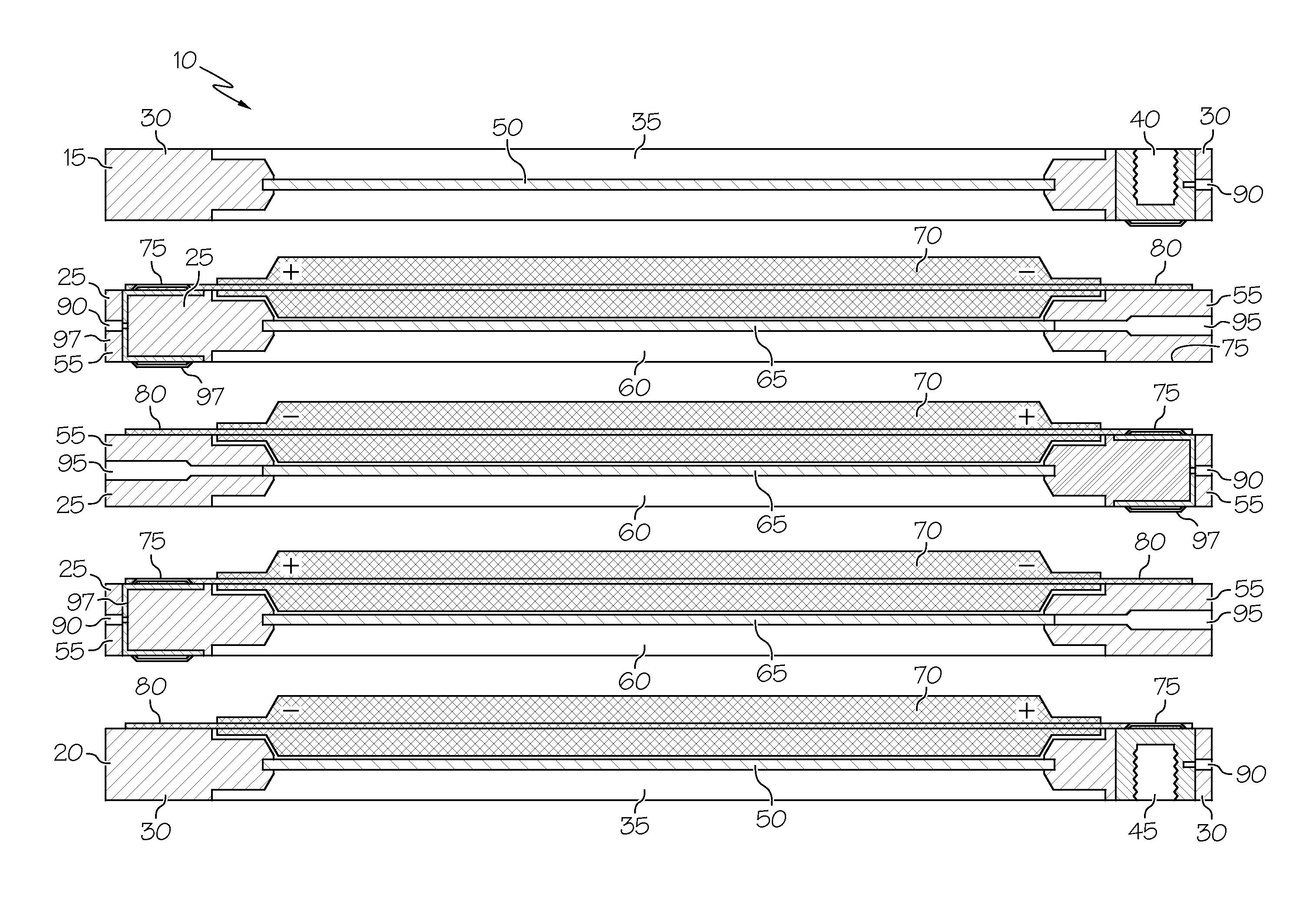
[0028]The integrated cooling fin and frame provides electrical isolation and effectively manages the heat transfer from the battery cell. The integrated cooling fin and frame electrically isolates the cell edge from the cooling fin by covering the edge of the cooling fin with the frame. The integrated cooling fin and frame eliminates the need to tape the edges of the battery cells to prevent arc flashing. The thermally conductive material of the cooling fin regulates the heat transfer from the encapsulated cell. The integrated cooling fin and frame reduces the number of separate parts, simplifying the assembly process. It allows the use of either welded or mechanical connections in making the battery cell stack. The integrated cooling fin and frames also improve the pressure distribution in the battery cell stack.

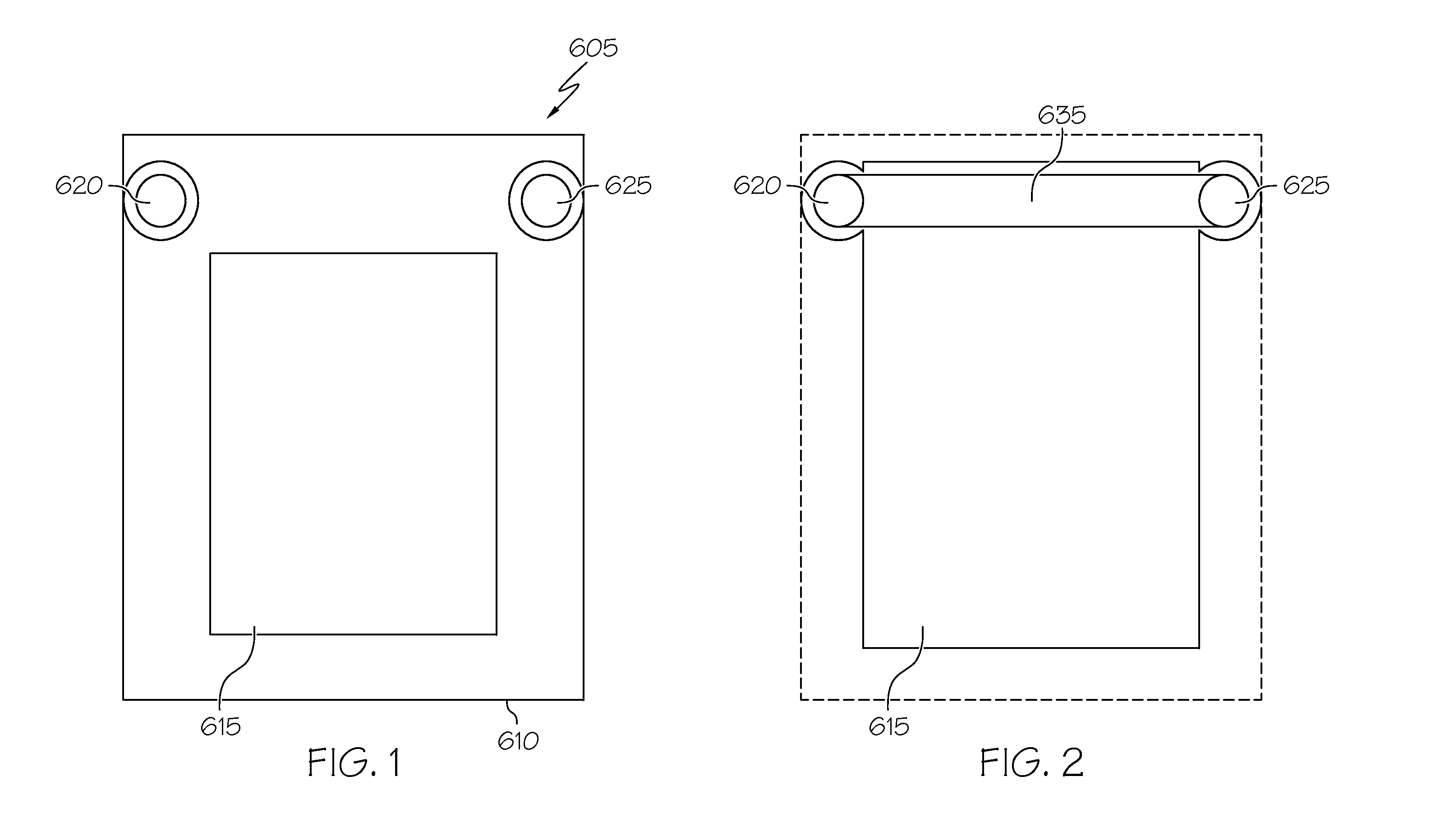
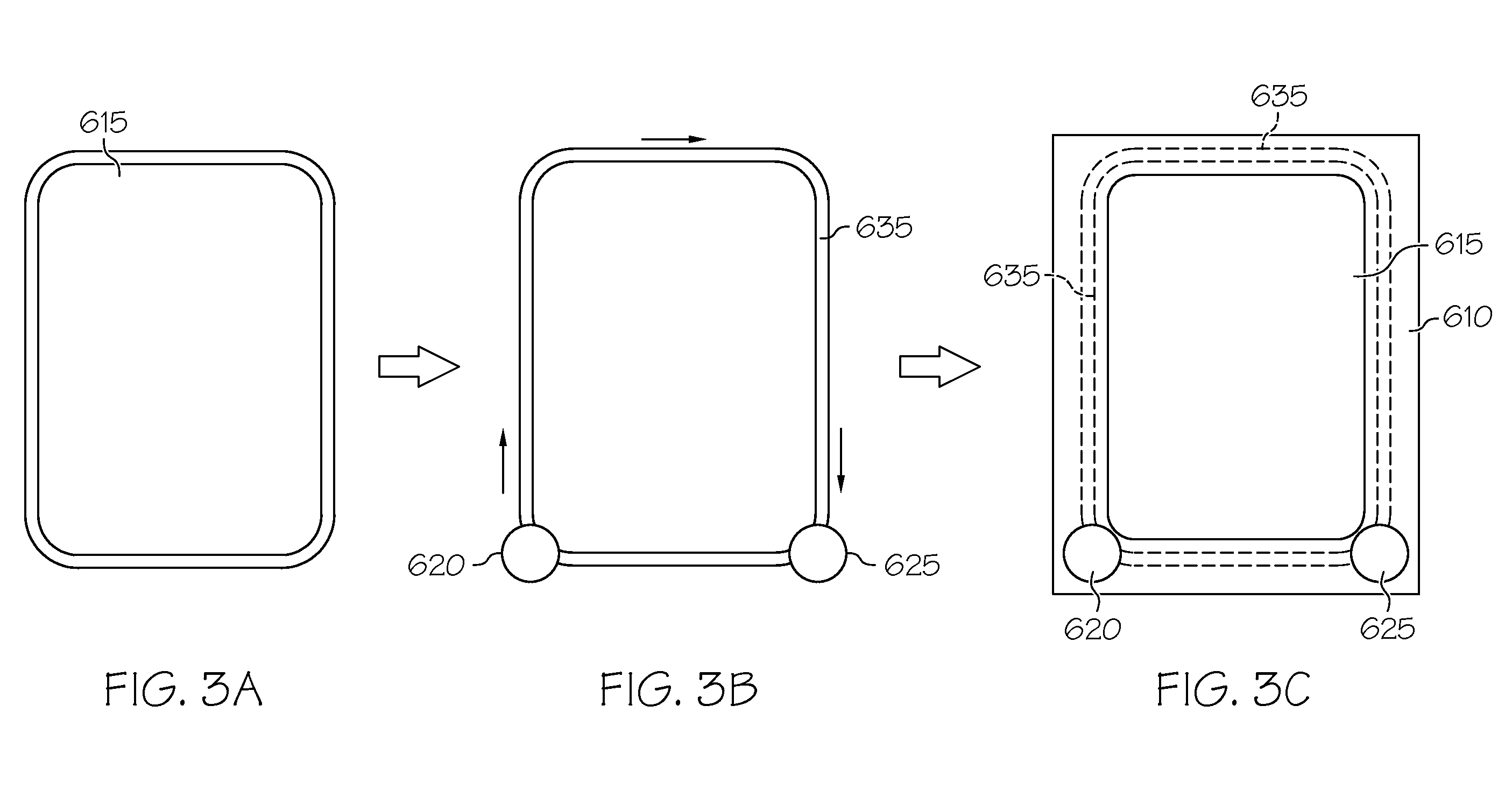
[0029]As shown in FIGS. 1-5, the integrated cooling fin and frame 605 includes a frame 610 and cooling fin 615. There is a fluid inlet 620 and fluid outlet 625 for the cool...


PUM

PropertyMeasurementUnit
spring forceaaaaaaaaaa
voltageaaaaaaaaaa
thermally conductiveaaaaaaaaaa

Abstract

An integrated cooling fin and frame is described. The integrated cooling fin and frame includes a cooling fin having a cooling channel adjacent to at least one edge, the cooling channel having an inlet and an outlet; and a frame around the cooling fin and covering the edges of the cooling fin, the frame having an opening for the inlet and outlet of the cooling channel. A battery pack containing the integrated cooling fin and frame and a method of making the integrated cooling fin and frame are also described.

Description

STATEMENT OF RELATED CASES[0001]This application is related to U.S. Ser. No. 12 / 853,462, entitled INTEGRATED STACKABLE BATTERY (Attorney Docket P009089-BAT-CHE), filed on Aug. 10, 2010, which is incorporated herein by reference.BACKGROUND OF THE INVENTION[0002]This invention relates generally to battery packs and more particularly to an integrated cooling fin and frame for battery packs.[0003]Currently, the battery cells in some battery packs are positioned in frames which are used to house the cells, cooling fins (plates), and expansion material, such as foam sheets. However, in some arrangements, these individual components can slide relative to one another which increases the dimensional variation of the battery pack. In addition, the movement potentially exposes the edges of the cell to the cooling fins, which can result in arc flashing.[0004]Therefore, there is a need for a battery pack that reduces the likelihood of arc flashingSUMMARY OF THE INVENTION[0005]The present inventi...

Claims


Application Information

Patent Timeline
Patent Type & Authority Applications(United States)
IPC IPC(8): H01M10/50B21D53/02F28F7/00H01M50/211H01M50/296
CPCY10T29/4935H01M10/504F28F3/086F28F2280/04H01M10/5004H01M2/1077H01M10/5059H01M10/5046H01M10/653H01M10/6551H01M10/6557H01M10/613Y02E60/10Y02P70/50H01M50/296H01M50/211
Inventor ODUMODU, KENNEDY U.
Owner GM GLOBAL TECH OPERATIONS LLC
Why Eureka
Try Eureka