bone conduction device having an integrated housing and vibrator mass

a technology vibrator mass, which is applied in the field of bone conduction device having an integrated housing and vibrator mass, can solve the problems of conductive hearing loss, hearing sensation, and impeded normal mechanical pathways that provide sound to hair cells in the cochlea

Active Publication Date: 2012-04-12
COCHLEAR LIMITED
View PDF7 Cites 31 Cited by
  • Summary
  • Abstract
  • Description
  • Claims
  • Application Information

AI Technical Summary

Benefits of technology

This patent describes two types of bone conduction hearing devices: 1. A device that has a small vibrating part called a viler that moves when it receives sounds. It also has a housing which holds these parts and can be worn on the head like glasses. When the viler moves, it sends out tiny waves that help people hear better. 2. Another type of device that works similar to the first but includes a battery inside the housing. These batteries provide energy to make sure the device always runs smoothly.

Problems solved by technology

The technical problem addressed in this patent text relates to providing effective treatment options for individuals with conductive hearing loss who cannot benefit from traditional methods like cochlear implants or hearing aides. There are several alternative solutions mentioned including bone conducting hearing aids and cross aids for single-sided deaf individuals but each has its limitations.

Method used


Image

  •  bone conduction device having an integrated housing and vibrator mass
  •  bone conduction device having an integrated housing and vibrator mass
  •  bone conduction device having an integrated housing and vibrator mass

Examples


Embodiment Construction

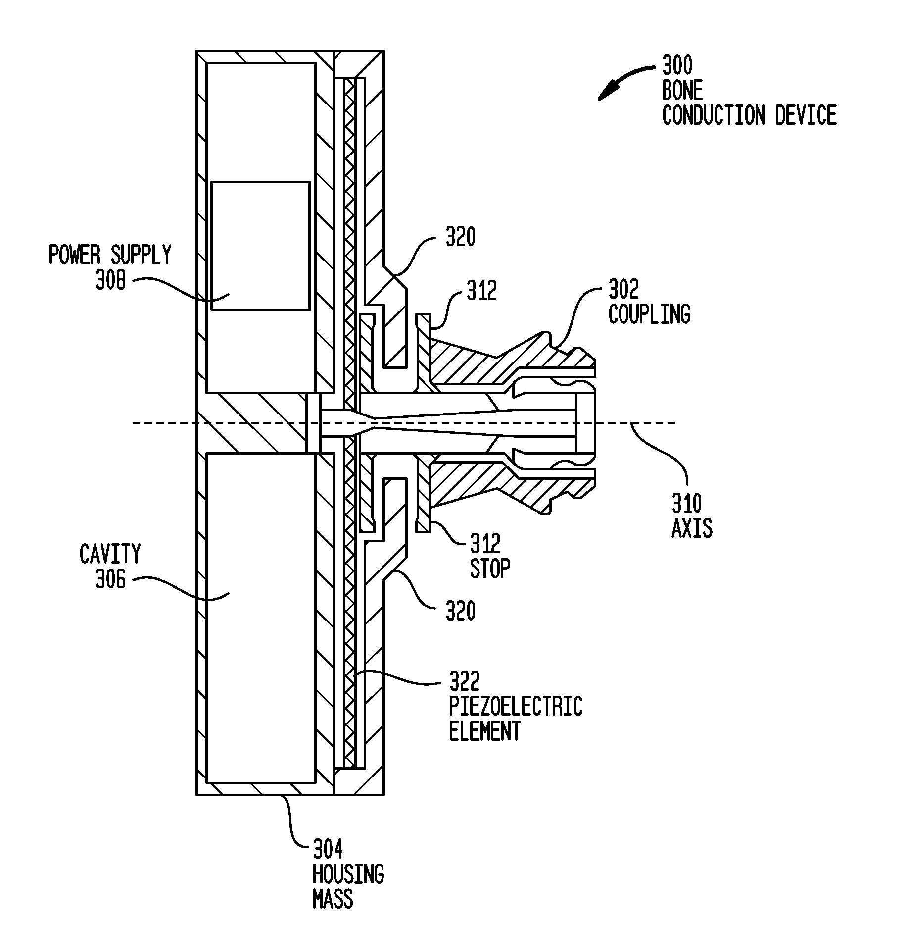
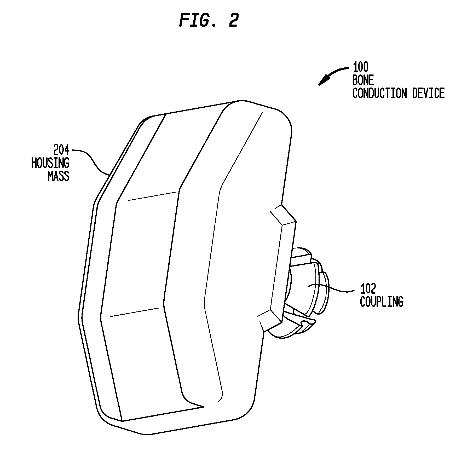
[0021]Embodiments of the present invention are generally directed to a bone conduction device for converting a received sound signal into a mechanical force for delivery to a recipient's skull. The bone conduction device comprises a vibrator configured to vibrate in response to sound signals received by the device, and an integrated housing and vibrator mass attached to the vibrator. The integrated housing and vibrator mass, referred to herein as a housing mass, is configured to house one or more operational components of the device. In certain embodiments, the housing mass comprises a substantially rigid and contiguous structure attached to the vibrator. The housing mass moves in response to the vibration of the vibrator to generate a mechanical force. The device further comprises a coupling configured to attach the device to a recipient so as to deliver the mechanical force generated by the housing mass and vibrator to the recipient's skull.

[0022]As noted above, bone conduction de...


PUM


Abstract

A bone conduction hearing aid device comprising a vibrator configured to vibrate in response to sound signals received by the device. The device further comprises a housing mass forming a housing for one or more operational components of the device, wherein the housing mass is attached to the vibrator so as to move in response to the vibration. The device also comprises a coupling configured to attach the device to a recipient so as to deliver the generated mechanical to the recipient's skull.

Description


Claims


Application Information

Patent Timeline
Owner COCHLEAR LIMITED
Why Eureka
Try Eureka