Integrated gas sparger for an immersed membrane

a gas sparger and membrane technology, applied in the field of gas spargers, can solve the problems of large bubbles that require the production of undesirable pressure spikes, and achieve the effect of reducing the number of bubbles

Active Publication Date: 2012-04-19
BL TECH INC
View PDF9 Cites 73 Cited by
  • Summary
  • Abstract
  • Description
  • Claims
  • Application Information

AI Technical Summary

Problems solved by technology

However, it was also noted in WO/2000/021890 that creating these large bub

Method used


Image

  • Integrated gas sparger for an immersed membrane
  • Integrated gas sparger for an immersed membrane
  • Integrated gas sparger for an immersed membrane

Examples


Embodiment Construction

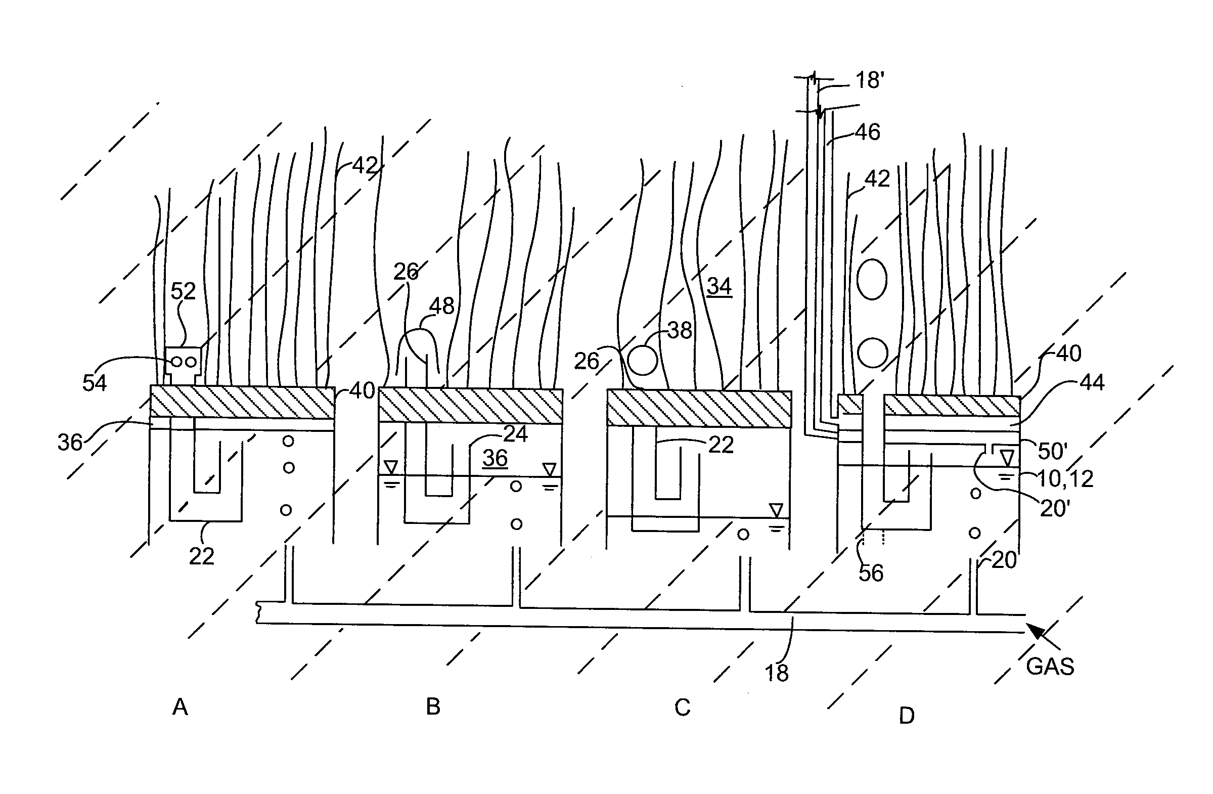
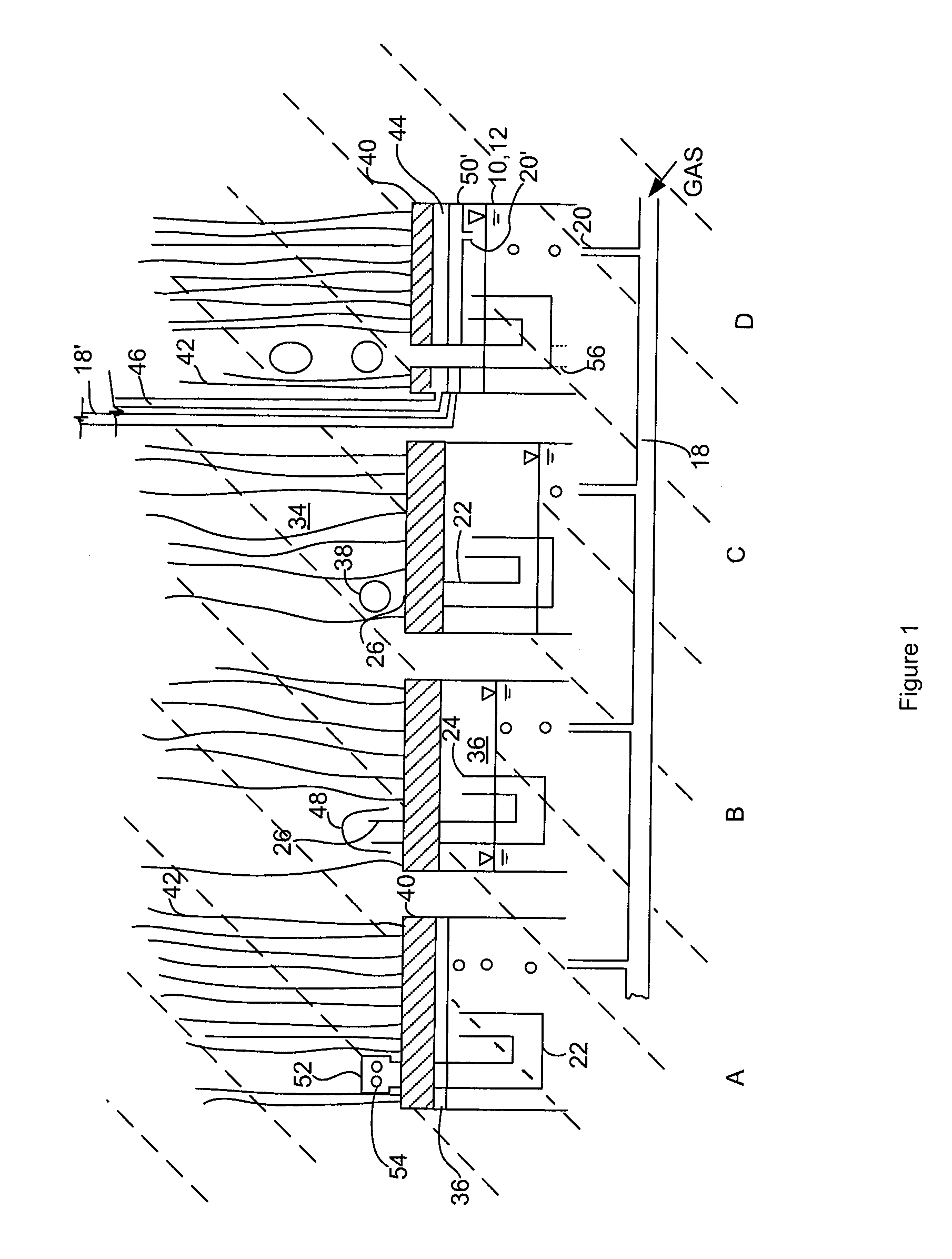
[0011]FIG. 1 shows four spargers 10 integrated with the potting heads 40 of four membrane modules A, B, C and D. A potting head 40 may alternately be called a header. Each potting head 40 is typically a block of a potting material such as a hardened resin. The ends of a plurality of hollow fiber membranes 42 are potted into the potting head. In the case of modules A, B and C, the ends of the membranes 42 are plugged in the potting head 40. A second potting head (not shown) is provided at the other ends of the membranes 42 to withdraw permeate from the lumens of the membranes 42, for example by way of a suction applied to a permeate cavity in communication with the lumens of the membranes 42. In module D, the ends of the membranes 42 are open to a permeate cavity 44 which is in turn connected to a permeate withdrawal pipe 46. The upper ends of the membranes 42 in module D may be individually plugged and loose (not held in a potting head), plugged collectively into one or more upper p...


PUM


Abstract

A gas sparger produces an intermittent flow of bubbles even if provided with a continuous gas flow. The sparger has a housing to collect a pocket of gas and a conduit to release some of the gas from the pocket when the pocket reaches a sufficient size. The housing is integrated with the potting head of a module. The conduit passes through the potting head.

Description

FIELD[0001]This specification relates to a gas sparger and to gas scouring to inhibit fouling of a filtering membrane.BACKGROUND[0002]The following background discussion is not an admission that anything discussed below is citable as prior art or common general knowledge.[0003]International PCT publication WO / 2000 / 021890 describes an aeration system for a submerged membrane module that has a set of aerators connected to an air blower, valves and a controller adapted to alternately provide a higher rate of air flow and a lower rate of air flow in repeated cycles to individual aerators. In an embodiment, the air blower, valves and controller, simultaneously provide alternating air flows to two or more sets of aerators such that while the total system air flow is constant, allowing the blower to be operated at a constant speed, each aerator receives a flow of air that varies over time. In some embodiments, the flow of air to an aerator occurs in repeated cycles of short duration. Trans...

Claims


Application Information

Patent Timeline
IPC IPC(8): B01D65/08B01F3/04B01F33/40
CPCB01D61/18B01D63/043B01F13/0255B01D2321/185B01D2313/26B01F33/406B01F35/71755B01D61/00B01D65/02B01D65/08B01D2313/21B01F23/2312
Inventor CUMIN, JEFFREY RONALDBAYLY, REID ALLYNHONG, YOUNGSECK
Owner BL TECH INC
Why Eureka
Try Eureka