Apparatus and method for ultrasonic spine treatment

a technology of ultrasonic spine and apparatus, which is applied in the field of apparatus for therapeutically treating bone structure using ultrasound, can solve the problems of increasing the inconvenience of patients and/or assistants, difficult manual positioning and maintaining a transducer adjacent to the patient, and immobilizing the patient during treatmen

Inactive Publication Date: 2012-05-03
BIOVENTUS LLC
View PDF4 Cites 10 Cited by
  • Summary
  • Abstract
  • Description
  • Claims
  • Application Information

AI Technical Summary

Problems solved by technology

As a result, the patient is, in effect, immobilized during treatment.
The longer the treatment period, the more the patient and / or the assistant is inconvenienced, and certain parts of the body, such as the back, cannot be reached by the patient with such a device, thus requiring the help of an assistant.
While the systems described in these patents relate to therapeutic methods and apparatus for ultrasonically treating injured bone, and describe basic mounting fixtures for use with a cast or limb for attaching the body applicator unit to the patient, they do not disclose signal generators and transducers, and attachments therefore, that permit placement of the body-applicator unit adjacent to various parts of the body that are either hard-to-reach or, because of the topology of the external skin location, make it difficult to manually position and maintain a transducer adjacent thereto.
Nor do these systems permit patient mobility during treatment.
Patients requiring spinal fusion have either neurological deficits or severe pain which has not responded to conservative treatment.

Method used


Image

  • Apparatus and method for ultrasonic spine treatment
  • Apparatus and method for ultrasonic spine treatment
  • Apparatus and method for ultrasonic spine treatment

Examples


second embodiment

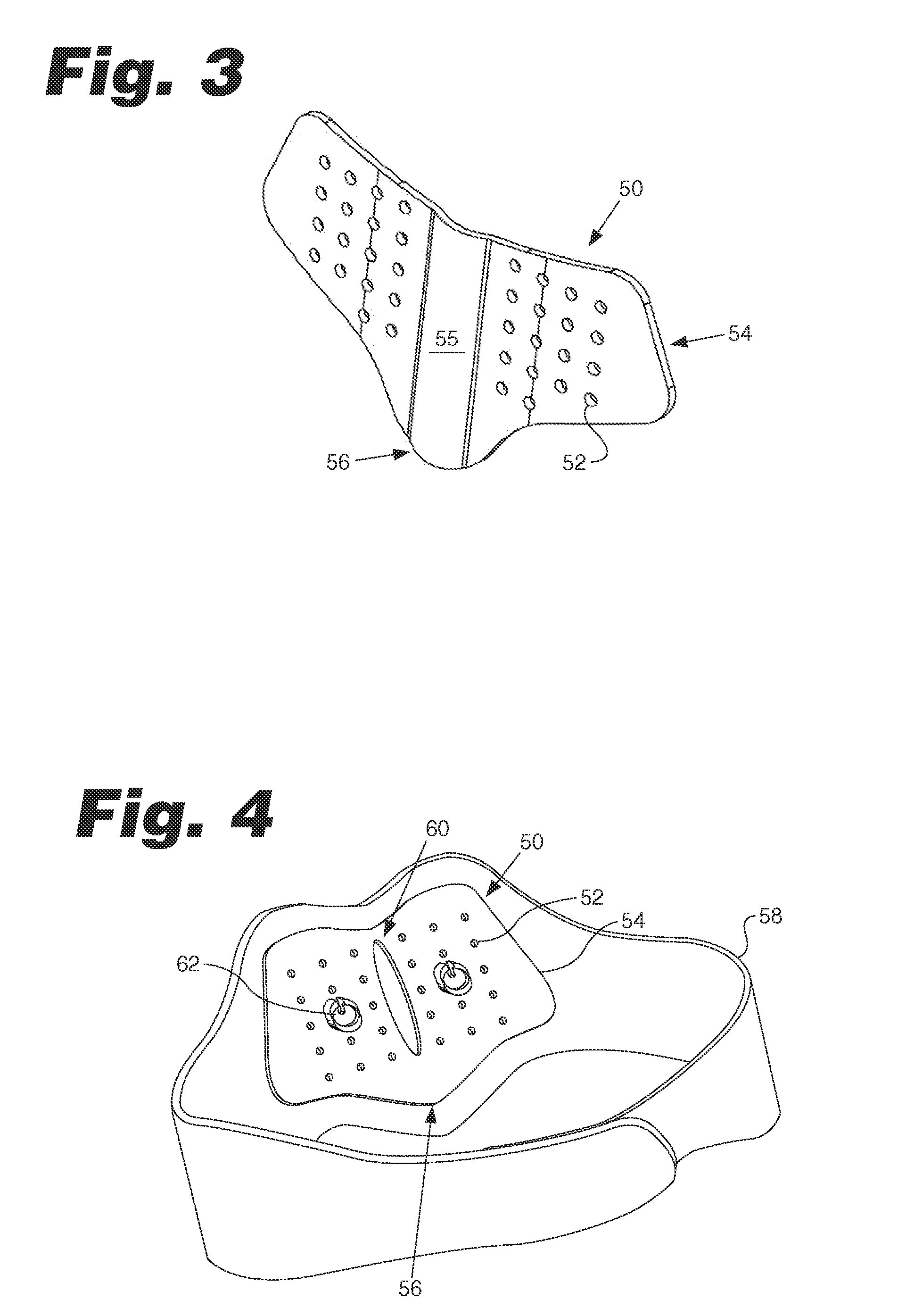
[0162]FIGS. 3 and 4 illustrate the treatment head module housing 50. The treatment head module housing 50 includes positioning holes 52, belt attachment members 54, and an alignment portion 56. A belt 58 is attached to the treatment head module housing 50 at the belt attachment members 54. Transducer holders 62 may be selectively positioned in the positioning holes 52. In the depicted embodiment, the positioning holes are arranged in a grid-like fashion. In some embodiments, the treatment head module housing 50 includes an incision window 60. In some embodiments, the treatment head module housing 50 may include a flex portion 55. The flex portion 55 is more flexible than the belt attachment members 54 and allows the treatment head module housing 50 to conform to a patient's back.

[0163]FIGS. 5-7 illustrate the transducer holder 62. The transducer holder 62 includes a dished portion or cup 66. The cup 66 is adapted to receive a transducer (not shown). One or more fasteners 64 may be u...

third embodiment

[0165]FIG. 9 is a top perspective view of a transducer holder in a The transducer holder 80 includes a first layer 82 and a second layer 84. The second layer 84 may include a dish portion or cup 86 adapted to receive a transducer.

fourth embodiment

[0166]FIG. 10 is a top perspective view of a transducer holder in a The transducer holder 90 includes a lower portion 92, an upper portion 94, and a fastener 96 to connect the upper and lower portions 92, 94. The upper portion 94 includes a dish portion or cup 95 adapted to receive the transducer. The upper and lower portions 92, 94 have a complementary shape and complementary teeth 98. The upper portion 94 may be rotated relative to the lower portion 92 to achieve a desired angle of the transducer.

[0167]FIGS. 11-15 illustrate a treatment head module housing 100. The treatment head module housing 100 includes a frame 110 and adjustment rails 112. In some embodiments, the treatment head module housing 100 includes an alignment feature 114. A pair of yoke 116 is removably attached to the frame 110. In some embodiments, one or more of the yokes may be permanently affixed to the frame 110. A horizontal adjustment knob 118 is used to adjust the yoke 116 in a medial / lateral direction. As...


PUM


Abstract

The present invention relates to an apparatus for therapeutically treating bone structure using ultrasound, and more particularly, the present invention relates to an apparatus with an attachment structure for treating bone injuries or a variety of musculoskeletal injuries and/or problems.

Description

CROSS-REFERENCE TO RELATED APPLICATIONS[0001]The present invention claims priority to US provisional application No. 61 / 109824 entitled “Apparatus and methods for ultrasonic spine treatment” filed on 30 Oct. 2008, which is herein incorporated in its entirety.FIELD OF THE INVENTION[0002]The present invention relates to an apparatus for therapeutically treating bone structure using ultrasound, and more particularly, the present invention relates to an apparatus with an attachment structure for treating bone injuries or a variety of musculoskeletal injuries and / or problems.BACKGROUND OF THE INVENTION[0003]The use of ultrasound to therapeutically treat and evaluate bone injuries is known. Impinging ultrasonic pulses having appropriate parameters, e.g., frequency, pulse repetition, and amplitude, for suitable periods of time and at a proper external location adjacent to a bone injury has been determined to accelerate the natural healing of, for example, bone breaks and fractures. For pat...

Claims


Application Information

Patent Timeline
Patent Type & Authority Applications(United States)
IPC IPC(8): A61N7/00
CPCA61H23/0245A61H2201/165A61N2007/0013A61N7/00A61H2205/081
Inventor SCHNEIDER, JOHN B.DE ANA, F. JAVIERPOUNDER, NEILL M.TANIS, KEVIN J.CONNER, CRAIG P.BULLIS, DANIEL R.CORS, MARK W.LEE, DANIEL J.DESMIDT, RACHEL E.REBACK, NICHOLAS S.LATHAM, STEPHEN A.
Owner BIOVENTUS LLC
Why Eureka
Try Eureka