Modular Humeral Head Resurfacing System

a humeral head and resurfacing technology, applied in the field of humeral head resurfacing, can solve the problems of increasing the amount of bone tissue removed, and affecting the resurfacing effect of the shoulder joint,

Inactive Publication Date: 2012-05-03
BIOMET MFG CORP
View PDF7 Cites 36 Cited by
  • Summary
  • Abstract
  • Description
  • Claims
  • Application Information

AI Technical Summary

Benefits of technology

[0016]Use of the present disclosure provides an apparatus and method for shoulder arthroplasty, and specifically, a modular humeral component and associated surgical components for use in shoulder arthroplasty. As a result, the aforementioned disadvantages associated with the currently available humeral components and associated surgical components for shoulder arthroplasty have been substantially reduced or eliminated.

Problems solved by technology

However, current prior art humeral components along with the associated surgical components and instruments utilized during shoulder arthroplasty suffer from many disadvantages.
However, such existing humeral components also exhibit several disadvantages.
Such humeral components increase the amount of bone tissue removed, while also increasing the labor and complexity of the shoulder arthroplasty.
However, the larger diameter stem also requires excess bone tissue to be removed which may not be practical in some patients.
While this type of humeral component addresses the amount of bone tissue removed, this type of system provides little versatility or adjustments to a surgeon performing the shoulder arthroplasty.
Moreover, this type of system does not provide additional enhanced fixation other than the planar intersecting fins.
Additionally, most prior art humeral components only rely on the stem to secure the humeral component into the intramedullary canal, via a cement mantle or bone attachment.
Although some humeral components may include a few longitudinal grooves and others may include both grooves and depressions on the medial surface, such surface enhancements only utilize or texture a portion of the medial surface, thereby not advantageously using the entire medial surface.

Method used


Image

  • Modular Humeral Head Resurfacing System
  • Modular Humeral Head Resurfacing System
  • Modular Humeral Head Resurfacing System

Examples


Embodiment Construction

[0039]The following description of the various embodiments concerning an apparatus and method for shoulder arthroplasty is merely exemplary in nature and is in no way intended to limit the disclosure, its application, or uses.

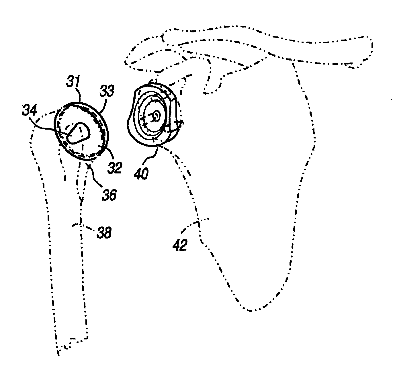
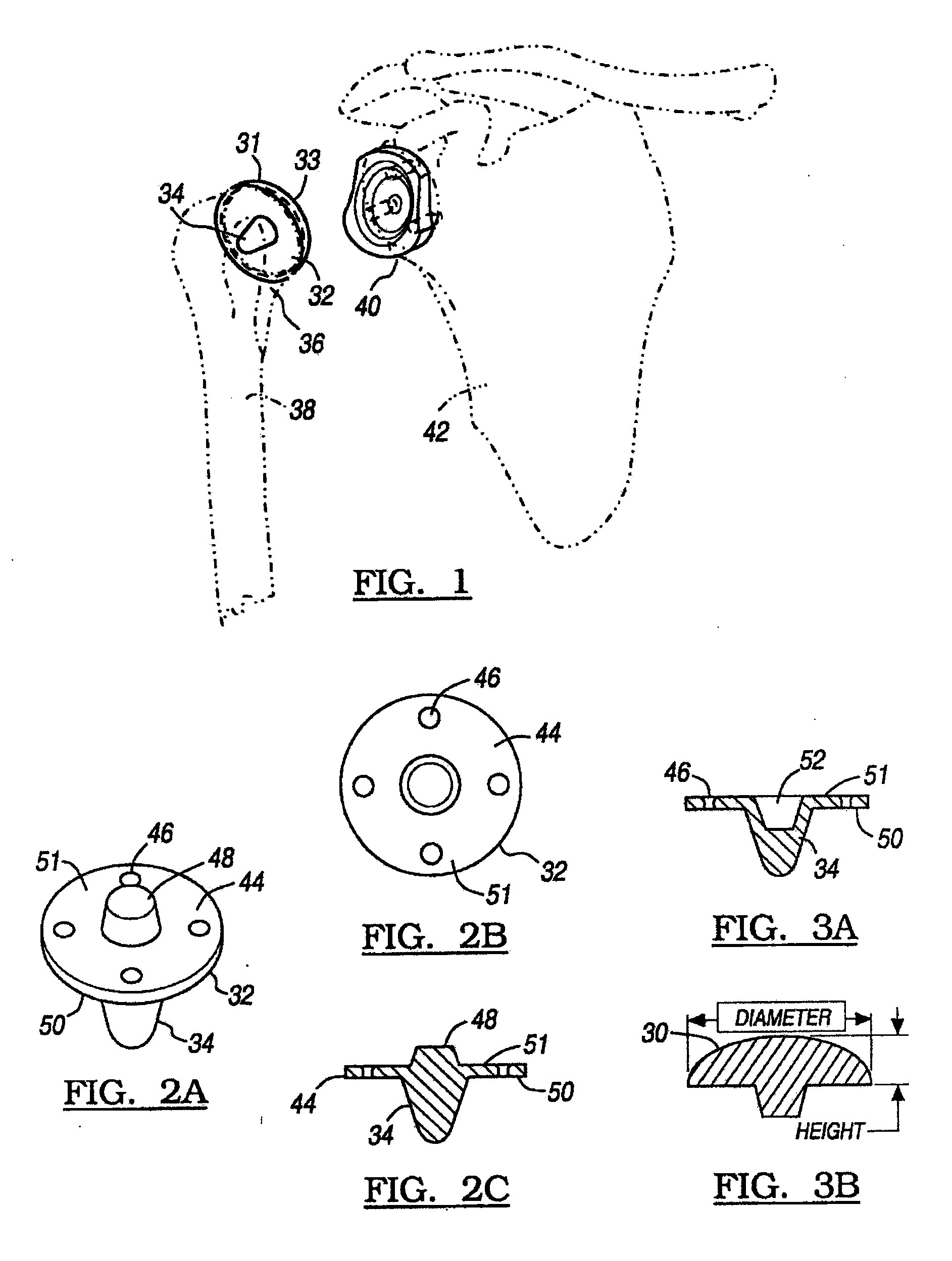
[0040]FIG. 1 depicts the components used in the shoulder arthroplasty of the current disclosure. As shown, the modular humeral component 31 has a base member 32 and a head member 33. The base member 32 has a fixation peg 34, which is used to attach the humeral component to the resected portion 36 of the humerus 38. If a total shoulder arthroplasty is performed, a glenoid component 40 is first implanted into the scapula 42 using techniques well known in the art. The glenoid component 40 is preferably of the type disclosed in U.S. Pat. No. 5,800,551, which is hereby incorporated by reference, or other suitable conventional glenoid components. The humeral component 31 is designed to allow rotational and transitional movement of the head member 33 with respect to t...


PUM

PropertyMeasurementUnit
diameteraaaaaaaaaa
radiusaaaaaaaaaa
diameteraaaaaaaaaa

Abstract

A set of surgical components for use in a joint arthroplasty to reconstruct a head of a joint is provided. The set of surgical components can include a head member having a first articulating surface opposite a first fixation surface. The first fixation surface can define a first portion that extends outwardly from the first fixation surface. The set of surgical components can include a base member having a fixation peg with three generally triangular fins and a second fixation surface defined as a recess within a top surface of the fixation peg. The first portion of the head member can be received within the recess of the base member to couple the head member to the base member.

Description

CROSS-REFERENCE TO RELATED APPLICATIONS[0001]This application is a divisional of U.S. patent application Ser. No. 10 / 930,044, filed on Aug. 30, 2004. U.S. patent application Ser. No. 10 / 930,044 is a continuation-in-part application of U.S. patent application Ser. No. 10 / 205,386 filed on Jul. 25, 2002, now issued as U.S. Pat. No. 6,783,549 on Aug. 31, 2004, which claims the benefit of U.S. Provisional Application No. 60 / 308,340, filed on Jul. 27, 2001. The disclosures of each of the above applications are incorporated herein by reference.BACKGROUND[0002]1. Field[0003]This disclosure relates generally to an apparatus and method for shoulder arthroplasty and, more particularly, to a humeral component and other associated surgical components and instruments for use in shoulder arthroplasty.[0004]2. Discussion of the Related Art[0005]A natural shoulder joint may undergo degenerative changes due to a variety of etiologies. When these degenerative changes become so far advanced and irrever...

Claims


Application Information

Patent Timeline
Patent Type & Authority Applications(United States)
IPC IPC(8): A61F2/40A61F2/30A61B17/16A61B17/86A61F2/00A61F2/02A61F2/46
CPCA61B17/1684A61F2310/00179A61F2/30767A61F2/40A61F2/4003A61F2/4081A61F2/4684A61F2002/30062A61F2002/30113A61F2002/30154A61F2002/30156A61F2002/30181A61F2002/30207A61F2002/3021A61F2002/30219A61F2002/30224A61F2002/30225A61F2002/30227A61F2002/30276A61F2002/30332A61F2002/30341A61F2002/30474A61F2002/30538A61F2002/30553A61F2002/30604A61F2002/30616A61F2002/30774A61F2002/30785A61F2002/30787A61F2002/30827A61F2002/30836A61F2002/30843A61F2002/30878A61F2002/30884A61F2002/30906A61F2002/4007A61F2002/4631A61F2210/0004A61F2220/0025A61F2220/0033A61F2230/0006A61F2230/0021A61F2230/0023A61F2230/006A61F2230/0067A61F2230/0069A61F2230/0086A61F2250/0006A61F2250/0008A61F2310/00017A61F2310/00023A61F2310/00029A61B17/86A61F2002/30217A61F2002/30339
Inventor STONE, KEVIN T.CORDARO, NICHOLAS M.
Owner BIOMET MFG CORP
Why Eureka
Try Eureka