Punch, implant and associated method

a technology of implants and humeral heads, applied in the field of orthopaedics, can solve the problems of reducing the load transfer capacity between the prosthesis and the humerus, and reducing the amount of time in the operating room. , the effect of reducing the amount of time to perform

Inactive Publication Date: 2006-07-06
DEPUY PROD INC
View PDF99 Cites 45 Cited by
  • Summary
  • Abstract
  • Description
  • Claims
  • Application Information

AI Technical Summary

Benefits of technology

[0038] Another technical advantage of the present invention includes reduced time in the operating room. For example, according to one aspect of the present invention, a plurality of trial sizes and implant sizes utilize a common size stem. Thus, the change in the trial size determined by a trial reduction will result in a smaller trial with the same size stem. The use of the same size stem will obviate the need of bone graft material being placed between the stem and the cavity and thus reduce the amount of time to perform such bone grafting in the operating room. Thus, the present invention reduces time in the operating room.
[0039] The technical advantages of the present invention further include a reduction in cost in performing the arthroplasty. For example, according to one aspect of the present invention, a plurality of trials and prostheses utilize a common stem. The stem may be provided with a common reamer. Since a common reamer can be used for various size trials and prostheses, the costs associated with a greater number of reamers can be reduced.
[0040] The technical advantages of the present invention include improved rotational stability of the surface replacement prosthesis. For example, according to one aspect of the present invention, a punch and an implant are provided with corresponding or matching fins in the punch and implant, with the punch making an impression to match the implant. Therefore, the present invention provides for rotational stability of a head resurfacing implant.
[0041] The technical advantages of the present invention, further include the ability of the present invention to permit accurate axial alignment of a surface replacement prosthesis. For example, according to one aspect of the present invention, a stop is provided on the punch to limit the depth of insertion of the punch into the pre-reamed hole of the stem of the orthopaedic implant. The stop includes first and second selectable positions. In the first position, the punch has a short

Problems solved by technology

However, the current trend is to use the cement to a lesser extent because of its tendency to lose adhesive properties over time.
There is also a possibility that cement contributes to wear debris within a joint.
Typically, however, arthritis of the gleno-humeral joint causes flattening of the humeral head with a large medial osteophyte.
The flat humeral head can cause voids in the bone under the prost

Method used


Image

  • Punch, implant and associated method
  • Punch, implant and associated method
  • Punch, implant and associated method

Examples


Embodiment Construction

[0094] Embodiments of the present invention and the advantages thereof are best understood by referring to the following descriptions and drawings, wherein like numerals are used for like and corresponding parts of the drawings.

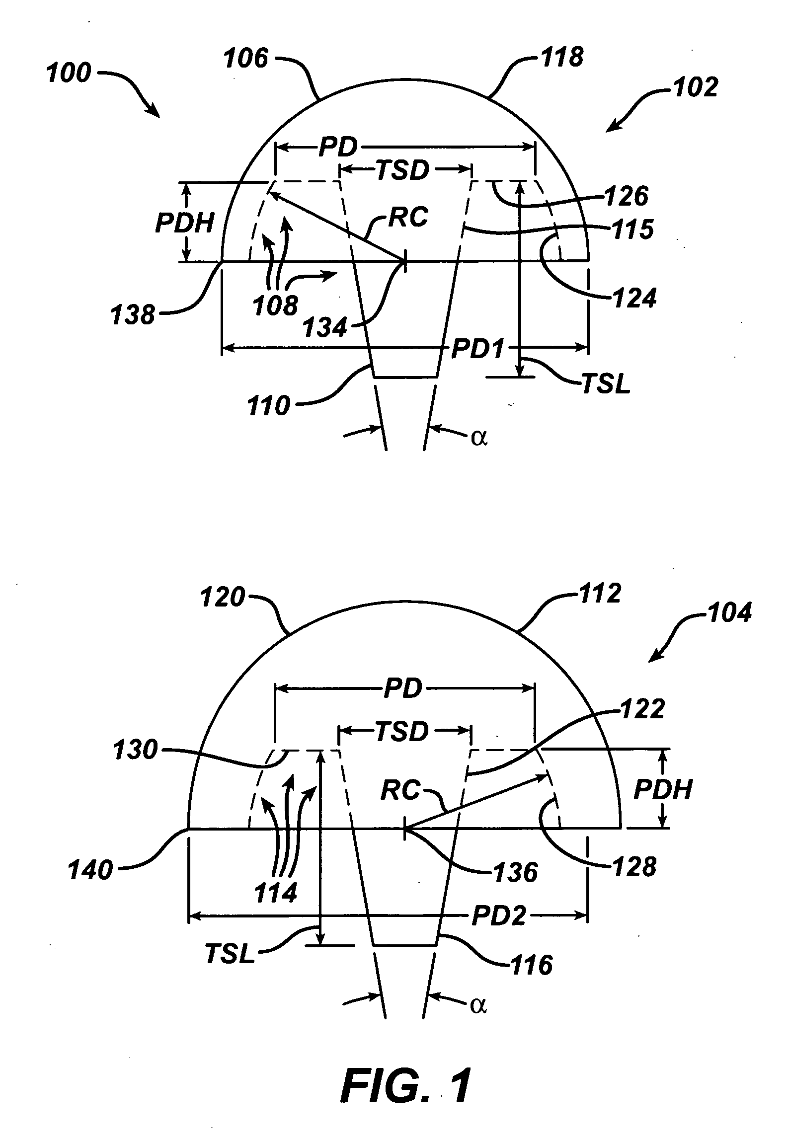
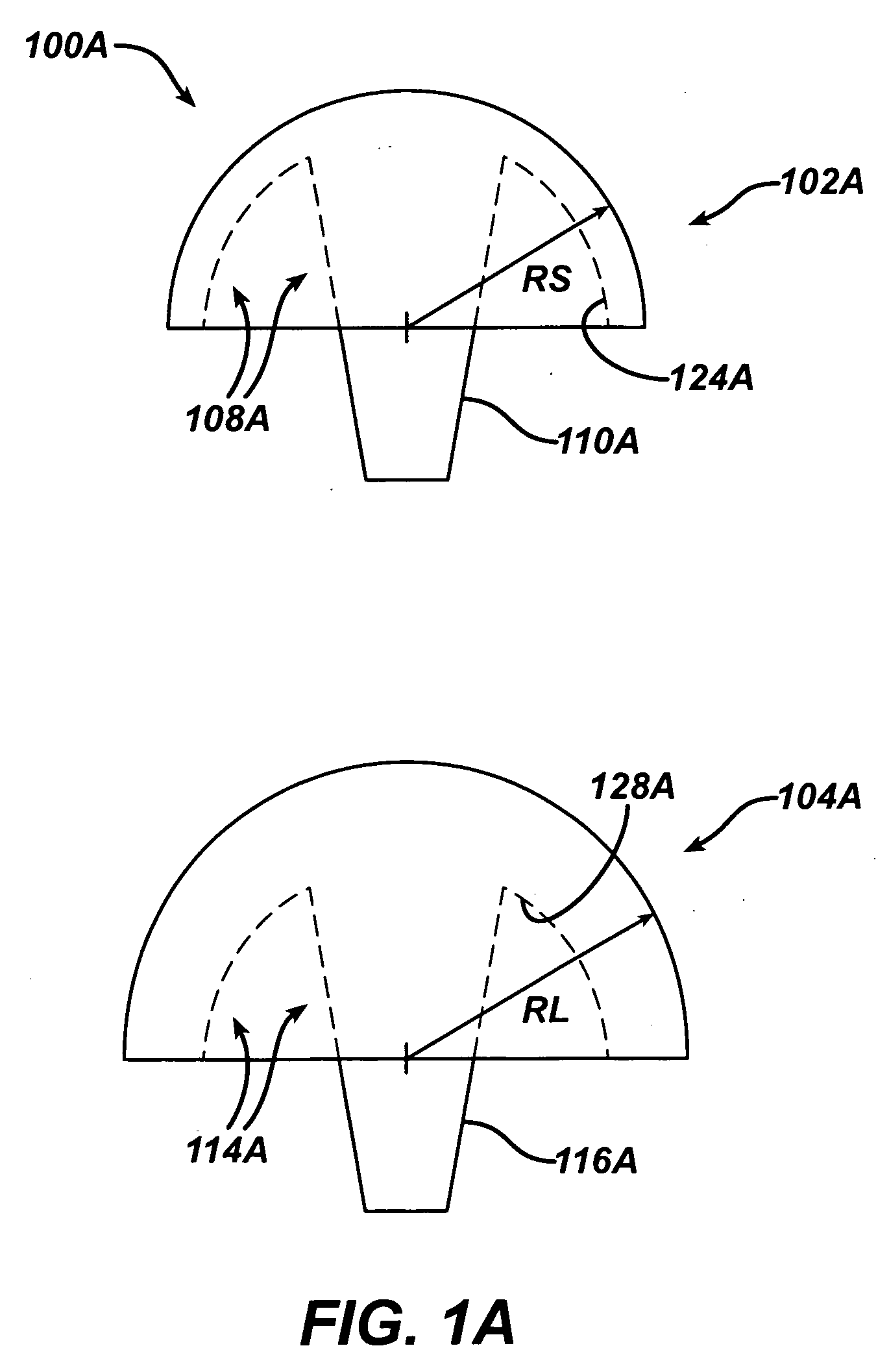
[0095] Referring now to FIG. 1, an embodiment of the present invention is shown as trial kit 100. The kit 100 is used for performing joint arthroplasty on a head of a long bone. The trial kit 100 includes a first trial 102 as well as a second trial 104. The first trial 102 includes a first trial articulating surface 106 and an opposed first trial mounting surface 108. The first trial mounting surface 108 includes a first trial location feature 110.

[0096] The second trial 104 includes a second trial articulation surface 112 and an opposed second trial mounting surface 114. The second trial mounting surface 114 includes a second trial location feature 116. The first trial articulating surface 106 and the second trial articulating surface 112 have different ge...


PUM


Abstract

An instrument for preparing a cavity for a stem of a prosthetic implant for use in performing joint arthroplasty on a head of a long bone is provided. The instrument includes a body and a punch extending from the body. The punch includes a portion of the punch having a shape similar to the stem of the implant.

Description

CROSS REFERENCE TO RELATED APPLICATIONS [0001] This application is a Continuation-in-Part of U.S. patent application Ser. No. 10 / 403,364 filed Mar. 31, 2003, entitled “PROSTHETIC IMPLANT, TRIAL AND ASSOCIATED METHOD”CROSS-REFERENCE TO RELATED APPLICATIONS [0002] Cross reference is made to the following applications: U.S. patent application Ser. No. 10 / 403,707 filed Mar. 31, 2003, entitled “ARTHROPLASTY SIZING GAUGE”, U.S. patent application Ser. No. 10 / 403,750 filed Mar. 31, 2003, entitled “ARTICULATING SURFACE REPLACEMENT PROSTHESIS”, U.S. patent application Ser. No. 10 / 403,577 filed Mar. 31, 2003, entitled “MODULAR ARTICULATING SURFACE REPLACEMENT PROSTHESIS”, U.S. patent application Ser. No. 10 / 403,710 filed Mar. 31, 2003, entitled “ARTHROPLASTY INSTRUMENT AND ASSOCIATED METHOD”, and U.S. patent application Ser. No. 10 / 403,708 filed Mar. 31, 2003, entitled “EXTENDED ARTICULATION ORTHOPAEDIC IMPLANT AND ASSOCIATED METHOD” which are incorporated herein by reference in their entitie...

Claims


Application Information

Patent Timeline
IPC IPC(8): A61F2/30A61B17/92A61B17/00A61B17/16A61B17/17A61B19/00A61F2/00A61F2/28A61F2/36A61F2/40A61F2/46
CPCA61B17/1604A61B17/1684A61B2017/00469A61B2019/303A61F2/3601A61F2/3603A61F2/4003A61F2/4607A61F2/4612A61F2/4684A61F2002/2835A61F2002/30163A61F2002/30245A61F2002/30299A61F2002/30616A61F2002/30841A61F2002/30878A61F2002/30884A61F2002/4007A61F2002/4623A61F2002/4677A61F2002/4681A61F2230/0028A61F2230/0071A61F2230/0093A61B2017/1778A61F2/4603A61F2002/30179A61B2090/033A61B17/1778
Inventor LONG, JACK F.IANNOTTI, JOSEPH PATTRICKWILLIAMS, GERALD R.
Owner DEPUY PROD INC
Why Eureka
Try Eureka