Apparatus, system and method for intraoperative performance analysis during joint arthroplasty

a performance analysis and intraoperative technology, applied in the field of apparatus, system and method for intraoperative performance analysis during joint arthroplasty, can solve the problems of undesirable wear of prosthetic components, poor performance, and localized high stress on prosthetic components

Active Publication Date: 2009-09-22
DEPUY PROD INC
View PDF13 Cites 46 Cited by
  • Summary
  • Abstract
  • Description
  • Claims
  • Application Information

AI Technical Summary

Problems solved by technology

If the ligaments and tendons around the knee are not properly balanced, the result may be poor performance, localized high stress on the prosthetic components and undesirable wear on the prosthetic components.
However, the surgeon does not necessarily obtain the feedback necessary during ligament release to help assess whether the release is adequate throughout the range of motion; full range of motion information can only be obtained with the trial in place.
Too much tension could result in premature wear of the prosthetic components, and too little tension can make the knee unstable.

Method used


Image

  • Apparatus, system and method for intraoperative performance analysis during joint arthroplasty
  • Apparatus, system and method for intraoperative performance analysis during joint arthroplasty
  • Apparatus, system and method for intraoperative performance analysis during joint arthroplasty

Examples


Embodiment Construction

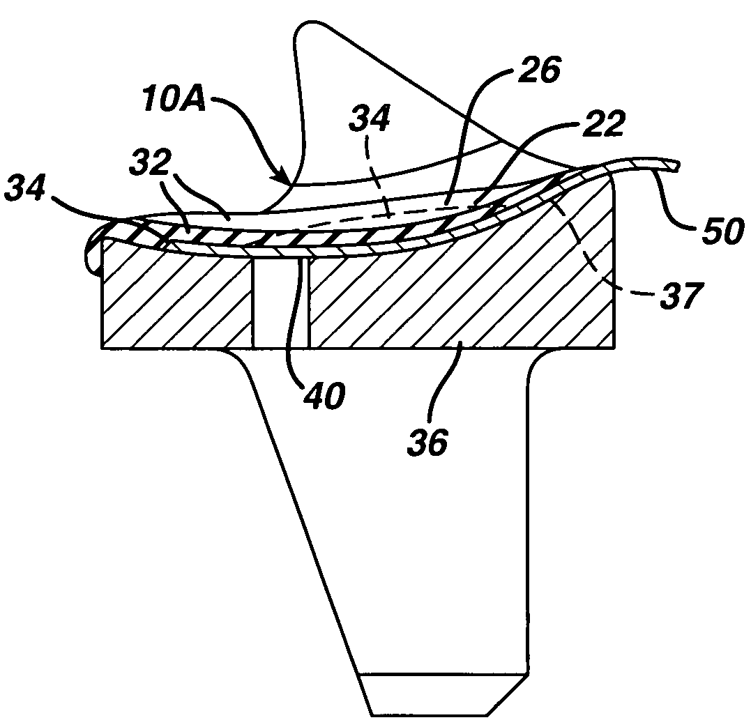
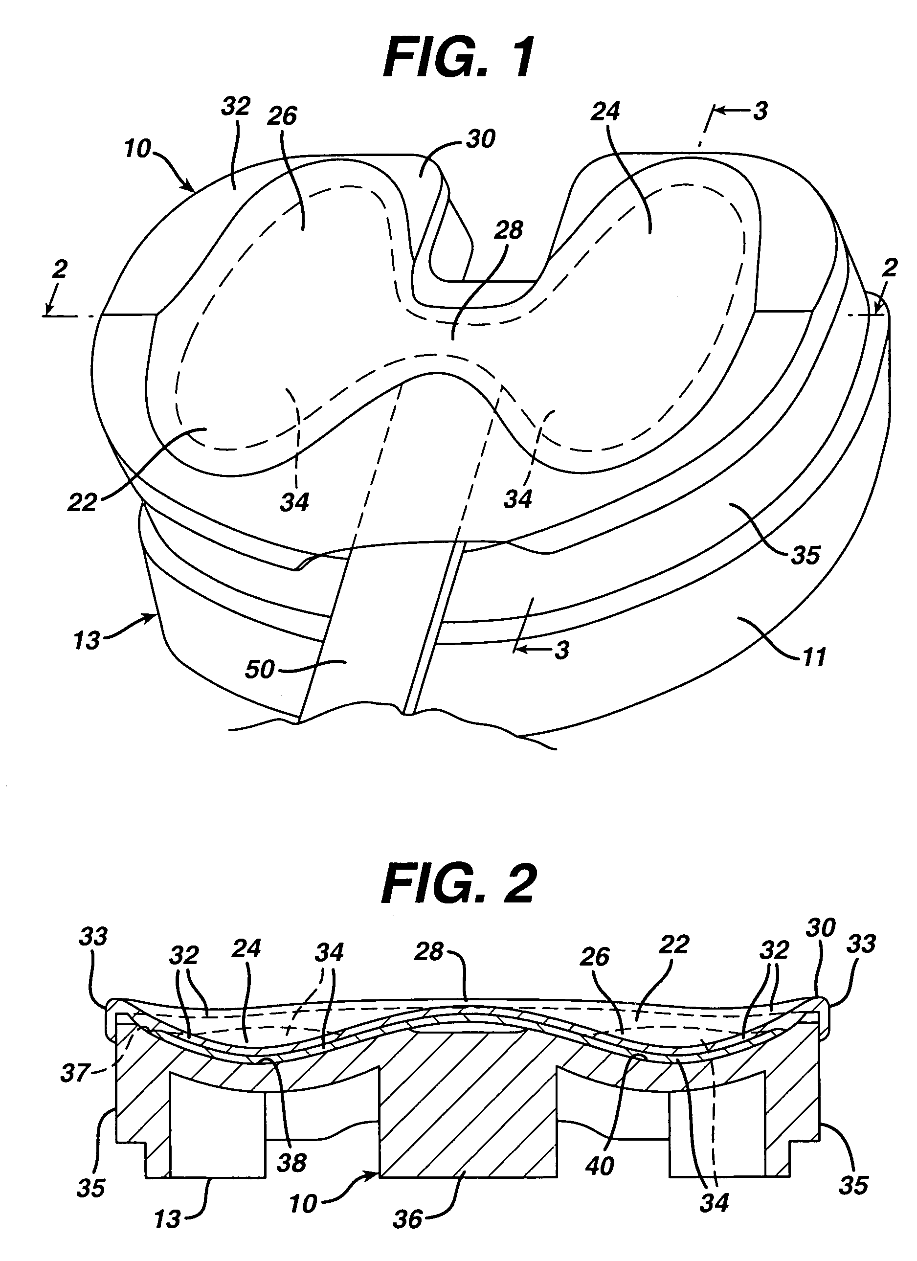
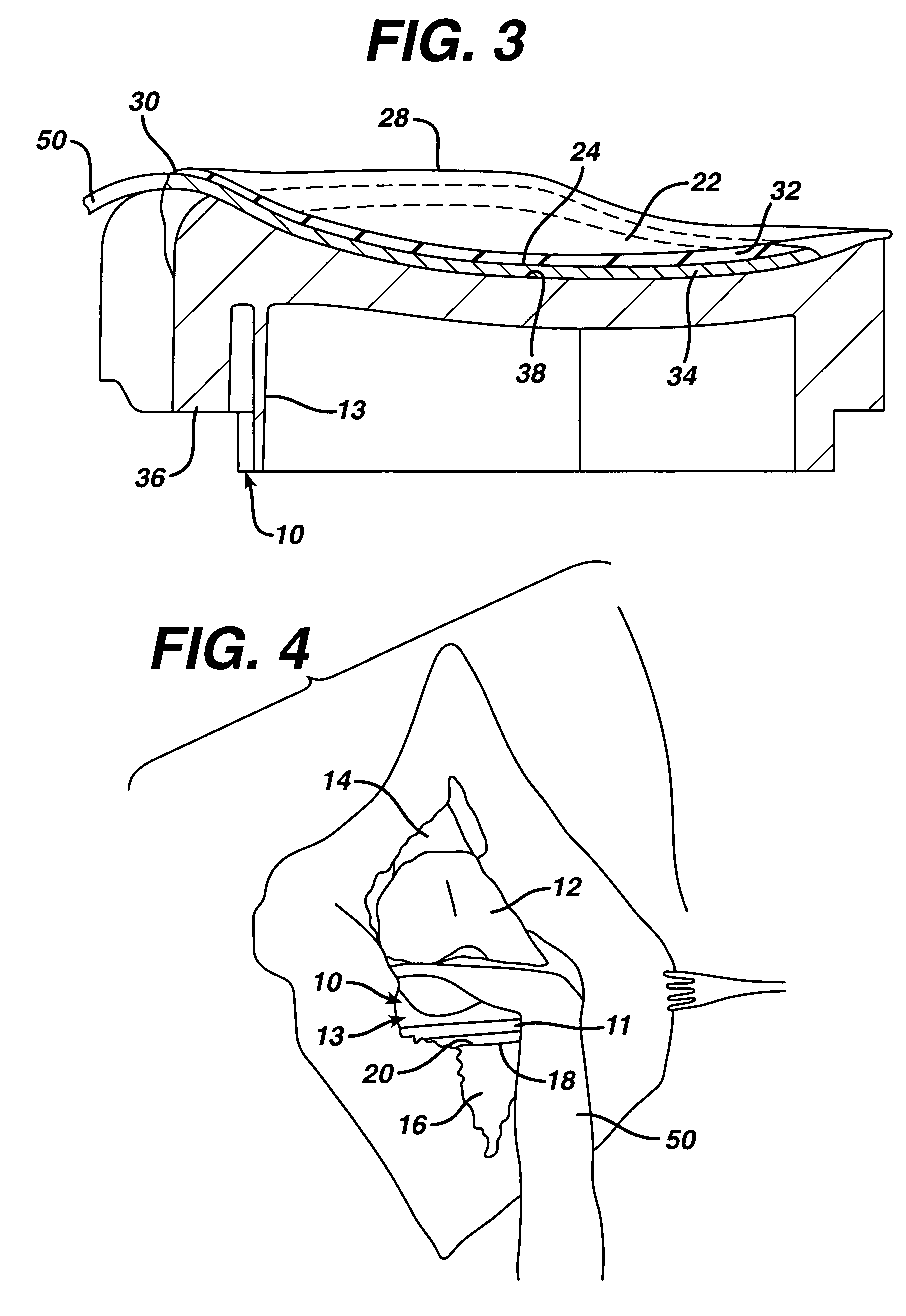
[0035]The first embodiment of the invention, illustrated in FIGS. 1-4, comprises an instrumented tibial trial insert 10. Another embodiment of an instrumented tibial trial insert is illustrated in FIGS. 5-7 at 10A. An embodiment of a joint tension sensor device is illustrated at 10B in FIGS. 15-17.

[0036]Each illustrated tibial trial insert 10, 10A, 10B is part of a tibial trial that also includes a tibial trial tray and stem, such as that shown at 11 in FIGS. 12-13. The entire tibial trial assembly is designated 13 in FIGS. 1 and 4. For a tibial trial insert like that shown in FIGS. 5-7, the tibial tray and stem would have a different design than for the design shown in FIGS. 12-13. Each tibial trial is part of a trial system that also includes a femoral trial, examples of which are illustrated in FIGS. 8-11 as 12 and 12A. The femoral trials could be one-piece or multiple piece parts of the system or kit. A surgical kit would typically include several different sizes of both tibial ...


PUM


Abstract

An instrumented joint trial has a polymer layer defining a curved contoured articulating surface. A curved contoured sensor array is positioned below the polymer layer. Other components of the joint trial, such as a body with a proximal curved contoured surface, are positioned below the sensor array. The device can be made by forming a sheet of the polymer over the curved contoured surface of the joint trial body and then adhering the sensor array to one curved contoured surface of the formed polymer. The sensor array conforms to the shape of the formed polymer layer. The system includes a mating joint trial. The device may be used by temporarily attaching the joint trial to a resected portion of bone and then articulating the joint with the instrumented trial in place.

Description

[0001]This application claims the benefit of U.S. Provisional Application No. 60 / 414,794, filed Sep. 30, 2002.BACKGROUND OF THE INVENTION[0002]The present invention relates to an apparatus, system and method for intraoperative performance analysis during joint arthroplasty.[0003]In total joint replacement or arthroplasty, bone orientation, selection of prosthetic joint components and soft tissue balancing are critical to the success of the procedure. Considering, for example, total knee arthroplasty, one or more cutting jigs are used to ensure that the distal end of the femur and proximal end of the tibia are cut in an orientation that will properly align the patient's bones. After the bones are cut or resected, prosthetic components are fixed to the femur, tibia and patella to define the prosthetic knee joint.[0004]A successful joint replacement or arthroplasty procedure results, in part, from selection of prosthetic joint components that are dimensioned and positioned to closely a...

Claims


Application Information

Patent Timeline
Patent Type & Authority Patents(United States)
IPC IPC(8): A61F2/38A61F2/00A61F2/46
CPCA61F2/4657A61F2/4684A61F2/389A61F2002/30133A61F2230/0015A61F2002/4688A61F2002/4696A61F2002/4697A61F2002/4666Y10S623/914
Inventor WASIELEWSKI, RAY C.
Owner DEPUY PROD INC
Why Eureka
Try Eureka