Movable audio/video communication interface system

a communication interface and audio/video technology, applied in the field of moving audio/video communication interface systems, can solve the problems of inability to create a viable personal communication and computing environment for collaboration among individuals, video conferencing systems cannot provide true sight lines between participants, and inability to make eye contact between participants

Inactive Publication Date: 2009-12-01
MORGAN STANLEY +1
View PDF21 Cites 248 Cited by
  • Summary
  • Abstract
  • Description
  • Claims
  • Application Information

AI Technical Summary

Benefits of technology

[0010]It is also an aspect of the present invention to provide an immersive type experience that can be easily integrated with other modes of working.
[0011]It is also an aspect of the present invention to provide an immersive type of experience without requiring large resources of floor space or specialized rooms.
[0012]The above aspects can be attained by a system that includes an assembly of multimodal displays and sensors mounted on a mechanical or robotic arm rising out of a desktop or other base. The arm moves the assembly so that it remains within position and orientation tolerances relative to the user's head as the user looks around. This lowers the requirements for sensor and display components so that existing sensors and displays can work well enough for the purpose. The arm does not need to be moved with great accuracy or maintain perfect on-axis alignment and uniform distance to the face. It must merely remain within tolerances. Kalman filters are applied to head motion to compensate for latency in the arm's tracking of the head. Tele-immersion is supported by the assembly because local and remote user's heads can be sensed and then represented to each other with true sight lines. By placing user interface transducers in motion, it becomes possible for users to move as they normally would in group interactions, particularly those including more than two participants. The invention provides a solution that is full duplex and yet has a small footprint. Users can be placed in any arrangement in virtual space. Because lighting and sound generation take place close to the user's head, the invention will not disrupt other activities in the local physical environment. Near-field speaker arrays supply immersive audio and a microphone array senses a users voice. In this way a user can be alerted by an audio event such as a voice to look in the direction of the event. Since the display will move to show what is present in that direction, the display need not be encompassing, or restrict access to the local physical environment, in order for the user to benefit from immersive virtual environments. The invention is also a haptic interface device; a user can grab the display / sensor array and move it about. The invention acts as a planar selection device for 3D data. This is important for volumetric data, such as MRI scan data. The physical position and orientation of display assembly provides planar selection and the need for mental rotation is reduced. Planar force feedback can also be used to allow a user to feel the center of density within a scalar field as resistance and curl. Users see not only each other through display windows, but can also see the positions and orientations of each others' planar selections of shared 3D models or data, so area of interest is communicated with minimal effort. The invention can also be used to subsume or simulate other user interface designs, such as command control rooms with multiple displays, wall-sized displays, “videobots,” or conventional desktop PC displays.

Problems solved by technology

These technologies suffer from an inability to create a viable personal communications and computing environment for collaboration among individuals in part because the underlying sensor and display components are not used in a way that allows them to perform well enough to meet human factors needs.
For instance, video conferencing systems cannot provide true sight lines between participants, because the camera and display are in different positions.
Therefore eye contact between participants is impossible.
Accurate sight lines require dynamic tracking of the positions of the eyes of users, and generally require that the visual scene presented to each eye be digitally reconstructed to be of the correct perspective, since it is difficult to consistently place a physical camera at the correct position to capture the proper perspective.
Several problems have made tele-immersion systems impractical.
One is that displays and eye-position sensors that are currently available or are foreseen to be available in the near future do not work well outside of narrow tolerances for the position and orientation of the user's head.
For instance, in order for participants to be able to be apparently placed close to each other in a shared virtual space, stereo vision must be supported, but for each eye to see a unique point of view, either some form of eyeware must be worn, or an autostereo display must be used, but available autostereo displays place restrictions on a user's head position.
Because of these problems, it has been difficult to design tele-immersion systems that combine true sight lines, full duplex (meaning that users can see each other without problems due to intervening machinery such as stereo viewing glasses), and flexible virtual placement (meaning that viewers can be placed at any distance, near or far, and in any arrangement.)
Another problem has been that tele-immersion systems have generally required dedicated rooms, which has limited their practicality.
The physical layout of tele-immersion instrumentation has placed restrictions on the virtual layout of participants in the virtual space.
The blue-c system generates true sight lines but places restrictions on relative placements of users in virtual space, cannot support high resolution sensing or display with currently available components, and requires dedicated rooms.
The HP Coliseum system cannot support true sight lines and generalized placement of participants at the same time.

Method used


Image

  • Movable audio/video communication interface system
  • Movable audio/video communication interface system
  • Movable audio/video communication interface system

Examples


Embodiment Construction

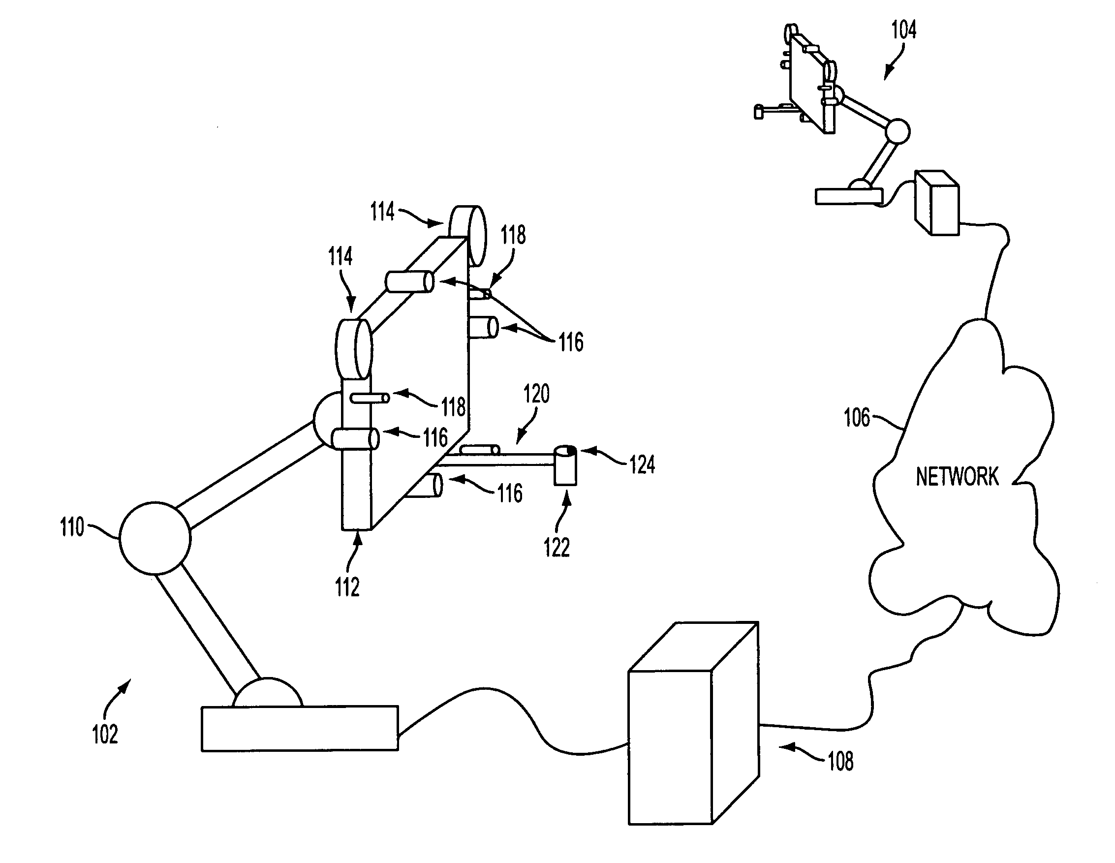
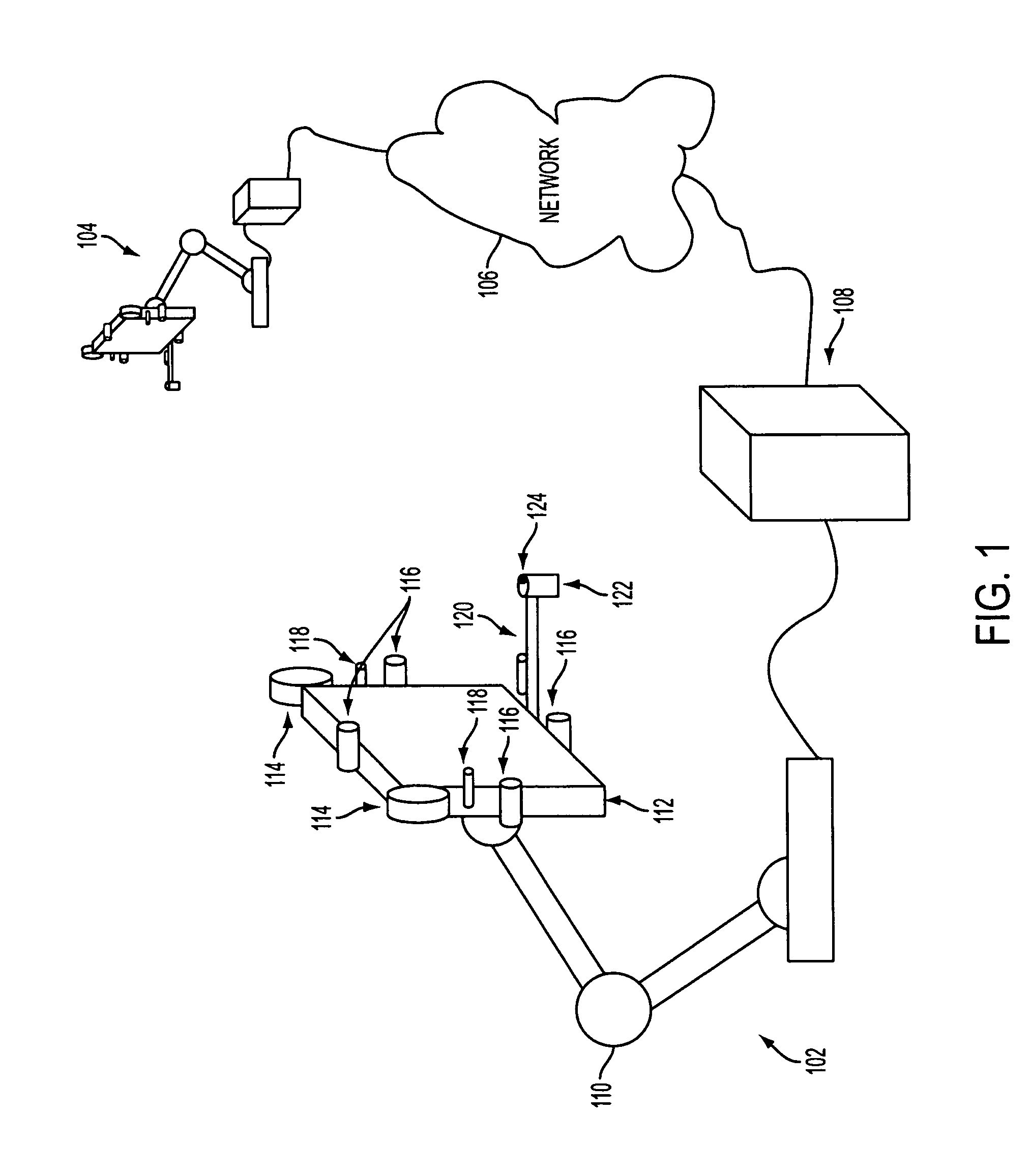
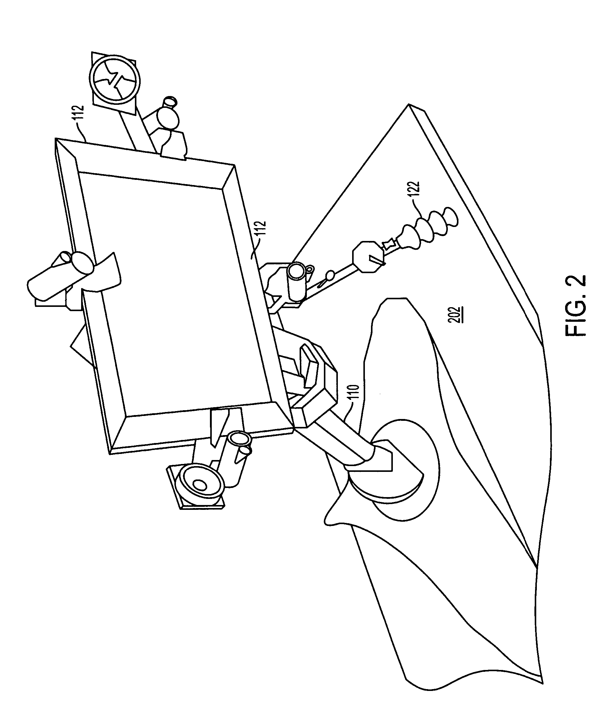
[0028]The present invention, which can also be called a Compact, Collaborative, Desktop, Explorer (COCODEX), is a user interface technology that can provide a solution to some of the most important and longest standing problems in Virtual Reality, Tele-immersion, 3D visualization, and video teleconferencing technologies. The invention includes an assembly of display and sensor components mounted on a mechanical arm that allows the assembly to move to a wide variety of locations around a user's head. Because the display and sensors are mobile, it is possible to keep them within constrained positions or tolerances relative to the user's face or head as the user looks around, thus making a variety of functions reliable that are not reliable in other configurations. These include auto-stereo display effects, 3D audio without headphones, machine vision analysis of the user's face, illumination of the face, audio sensing of the voice, and so on. This can be accomplished without physical c...


PUM


Abstract

A system that includes a desk top assembly of a display and sensors mounted on a robotic arm. The arm moves the assembly so that it remains within position and orientation tolerances relative to the user's head as the user looks around. Near-field speaker arrays supply audio and a microphone array senses a user's voice. Filters are applied to head motion to reduce latency for arm's tracking of the head. The system is full duplex with other systems allowing immersive collaboration. Lighting and sound generation take place close to the user's head. A haptic interface device allows the user to grab the display / sensor array and move it about. Motion acts as a planar selection device for 3D data. Planar force feedback allows a user to “feel” the data. Users see not only each other through display windows, but can also see the positions and orientations of each others' planar selections of shared 3D models or data.

Description

CROSS-REFERENCE TO RELATED APPLICATION[0001]This application is related to and claims priority to U.S. provisional application entitled A Movable Audio Video Communication Interface System having Ser. No. 60 / 621,085, by Lanier, filed Oct. 25, 2004 and incorporated by reference herein.BACKGROUND OF THE INVENTION[0002]1. Field of the Invention[0003]The present invention is directed to a system for immersing a user into a multi-dimensional collaborative environment using position tracking to adjust a position of a display displaying a 3D scene and / or other participants in the collaboration.[0004]2. Description of the Related Art[0005]In the past a number of different technologies have been used to help people collaborate at a distance by coupling them together in some sort of common environment. These technologies have includes conference telephone systems, video telephones, networked head mounted displays, collaborative document software, etc. These technologies suffer from an inabili...

Claims


Application Information

Patent Timeline
Patent Type & Authority Patents(United States)
IPC IPC(8): G09G5/00
CPCG06F1/1601G06F1/1605G06F3/012G06F3/011G06F2200/1612
Inventor LANIER, JARON
Owner MORGAN STANLEY
Why Eureka
Try Eureka