Surgery system

a technology of surgery system and guiding system, which is applied in the field of surgery system, can solve the problems of limiting the range, adding complexity to the system, and inaccuracy in surgery, and achieves the effects of reducing the lifetime cost of the image-guided surgery system, reducing the cost of the system, and improving the life of the instrumen

Active Publication Date: 2010-05-25
STRYKER CORP
View PDF76 Cites 246 Cited by
  • Summary
  • Abstract
  • Description
  • Claims
  • Application Information

AI Technical Summary

Benefits of technology

[0011]It is an object of the invention to provide an image-guided surgery system which enables easy, fast and accurate initialization, calibration, and control of a series of image guided surgery instruments. This object is achieved by providing wireless instruments with several improvements. The instruments of this invention are wireless and have a bi-directional high speed communication system that allows communication between the instruments and a computer system in real time. The communication system consists of a high-speed, specific frequency or spread frequency, infrared or RF based signaling system located in the instruments

Problems solved by technology

Tethered instruments can add complexity to the system by limiting the range of motion of the instrument and adding additional wires and cables to route and negotiate during the surgery.
Limitations must be overcome by the surgeon and can lead to inaccuracies in the surgery.
However, if there is a flaw in the instrument due to a manufacturing flaw or a flaw caused during use, the software may not be able to recognize the instrument, thereby making rendering the instrument useless.
This process is lengthy and if not performed properly can result in inaccuracies in the imaging system.
The use

Method used


Image

  • Surgery system
  • Surgery system
  • Surgery system

Examples


Embodiment Construction

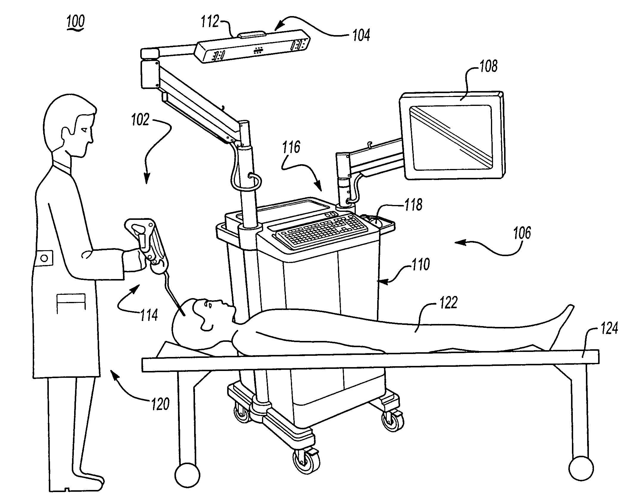
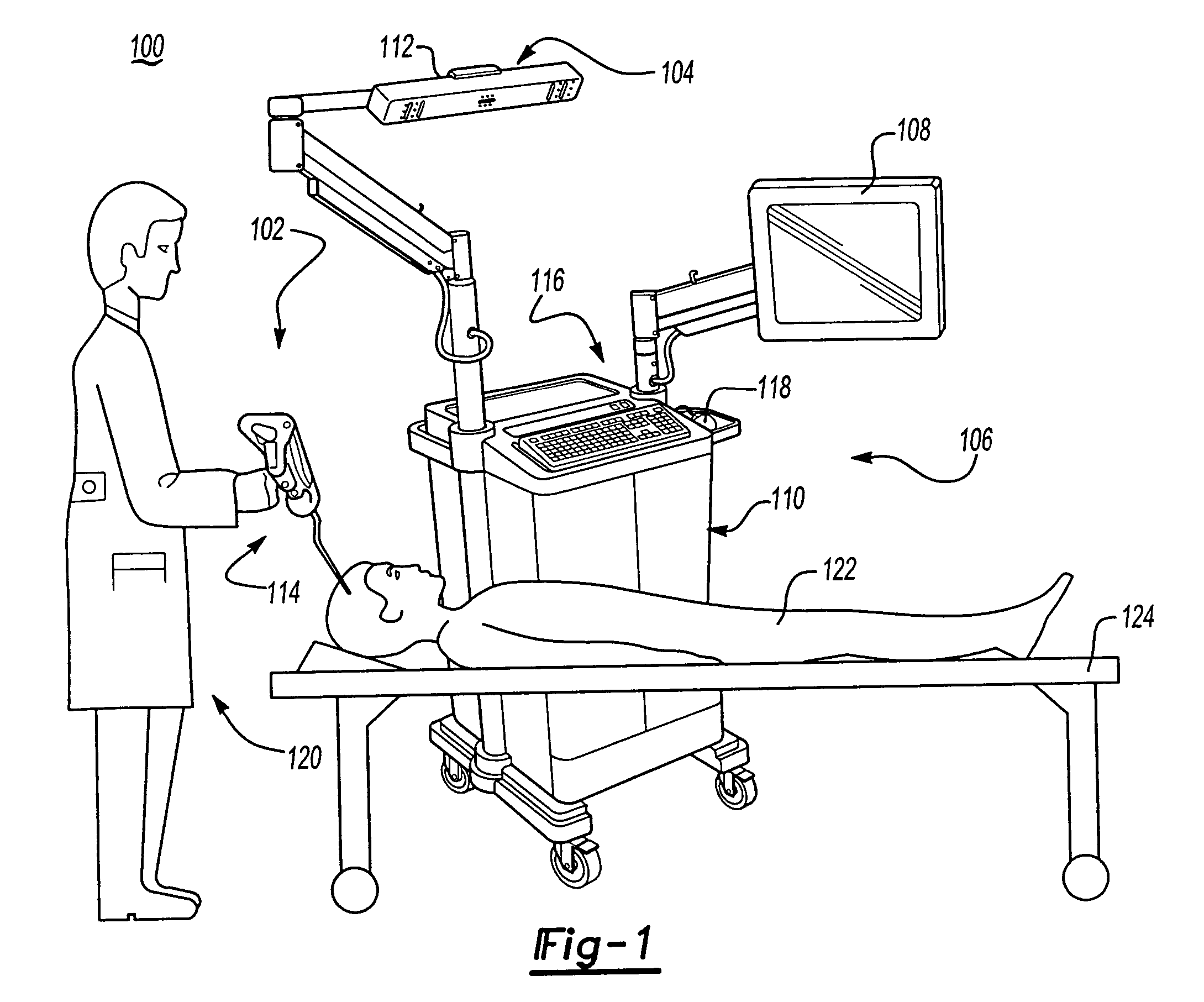
[0054]With reference to drawings and in operation, the present invention provides a surgery system 100 having at least one smart instrument 102. The surgery system 100 includes a sensor system 104 and a computer system 106. The computer system 106 includes a monitor 108. The computer system 106 is preferably housed in a computer cart assembly 110.

[0055]The sensor system 104 is coupled to the computer system 106 and is adapted to wirelessly transmit data back and forth between the at least one smart instrument 102 and the computer system 104 and to sense the position of the at least one smart instrument 102 (see below). Preferably, the sensor system 104 comprises a sensor array 112.

[0056]The smart instrument 102 is operated by an operator 120 to display a location of the smart instrument 102 relative to a patient 122 on a diagram, e.g., an image (such as an MRI or x-ray), picture, outline, line drawing, displayed on the monitor 108 during a surgical procedure.

[0057]With reference to ...


PUM


Abstract

A surgery system comprising at least one smart instrument, a computer system, and a sensor system adapted to wirelessly sense the position of the at least one smart instrument and to transmit position information to the computer system, wherein the sensor system includes a sensor array and the sensor array includes at least three linear CCD cameras and at least one infrared transceiver.

Description

[0001]This application is a divisional of U.S. application Ser. No. 09 / 764,609, filed on Jan. 17, 2001, and now abandoned, which claims priority from provisional application Ser. No. 60 / 178,377, filed on Jan. 27, 2000.BACKGROUND OF THE INVENTION[0002]1. Field of the Invention[0003]This invention relates generally to a surgery system. In particular this invention relates to a system for displaying and guiding a series of instruments to a surgical site located relative to a body of a patient.[0004]2. Description of Related Art[0005]Traditionally, an image-guided surgery system is used to display a position of a surgical instrument in an operating zone within the body of a patient. A number of frame and frameless stereotactic systems have been developed to assist surgeons during various procedures that require an instrument to travel to a target within a body. Typically, a surgeon analyzes images of the body using CT scans, MRI scans, or PET scans to determine a location of a target an...

Claims


Application Information

Patent Timeline
IPC IPC(8): A61B19/00A61B17/00G08C21/00G08C17/00G08C23/04
CPCA61B19/5244A61B19/52A61B19/44A61B19/26A61B19/56A61B2017/00212A61B2017/00725A61B2019/448A61B2019/507A61B2019/5255A61B2019/5257A61B2019/5268A61B2019/5272A61B2019/5445A61B2019/5479A61B2019/5483A61B2019/562A61B2090/3983A61B90/36A61B2034/2055A61B2034/2057A61B2034/2068A61B2034/2072A61B2090/3945A61B2090/3979A61B34/20A61B34/25A61B90/50A61B90/90A61B90/98A61B2034/107A61B2034/252
Inventor MALACKOWSKI, DONALD W.DE LA BARRERE, JOSE LUIS MOCTEZUMAHERSHBERGER, DAVID E.BOHRINGER, MARKUSFORST, PETERBUEHNER, ULRICHSTANGENBERG, MARTINCULP, JERRY A.WELTE, KLAUS
Owner STRYKER CORP
Why Eureka
Try Eureka