Extended articulation orthopaedic implant and associated method

a technology of extended articulation and orthopaedics, applied in the field of orthopaedics, can solve the problems of deterioration of the patient's rotator cuff, accelerated humeral articular destruction and erosion of the acromion, and significantly limited patient's range of motion, so as to achieve low friction bearing surface, minimal bone loss, and low friction bearing

Inactive Publication Date: 2009-04-14
DEPUY SYNTHES PROD INC
View PDF61 Cites 48 Cited by
  • Summary
  • Abstract
  • Description
  • Claims
  • Application Information

AI Technical Summary

Benefits of technology

[0026]The technical advantage of the present invention includes the ability to provide a low friction bearing surface between the greater tuberosity and the acromion. For example, according to one aspect of the present invention, a superior/lateral flange extends from a periphery of the hemispherical body of the prosthesis, which flange provides for extended articulation in the coracoacromial arch. Thus, the present invention provides a low friction bearing surface between the greater tuberosity and the acromion.
[0027]The technical advantages of the present invention ...

Problems solved by technology

However, the current trend is to use cements to a lesser extent because of their tendency to lose adhesive properties over time and the possibility that cement contributes to wear debris within a joint.
One such condition is the deterioration of the patient's rotator cuff.
Such articulation between these components accelerates humeral articular destruction and the erosion of the acromion and acromioclavicular joint.
Moreover, such bone-to-bone contact is extremely painful for the patient, thereby significantly limiting the patient's range of motion.
However, clinical experience has shown that such use of a large humeral head prosthesis (overstuffs) the shoulder joint thereby increasing soft tissue tension, reducing joint range of motion, and increasing shoulder pain.
Moreover, such use of an oversized prosthetic head fails to resurface the area of the greate...

Method used


Image

  • Extended articulation orthopaedic implant and associated method
  • Extended articulation orthopaedic implant and associated method
  • Extended articulation orthopaedic implant and associated method

Examples


Embodiment Construction

[0055]Embodiments of the present invention and the advantages thereof are best understood by referring to the following descriptions and drawings, wherein like numerals are used for like and corresponding parts of the drawings.

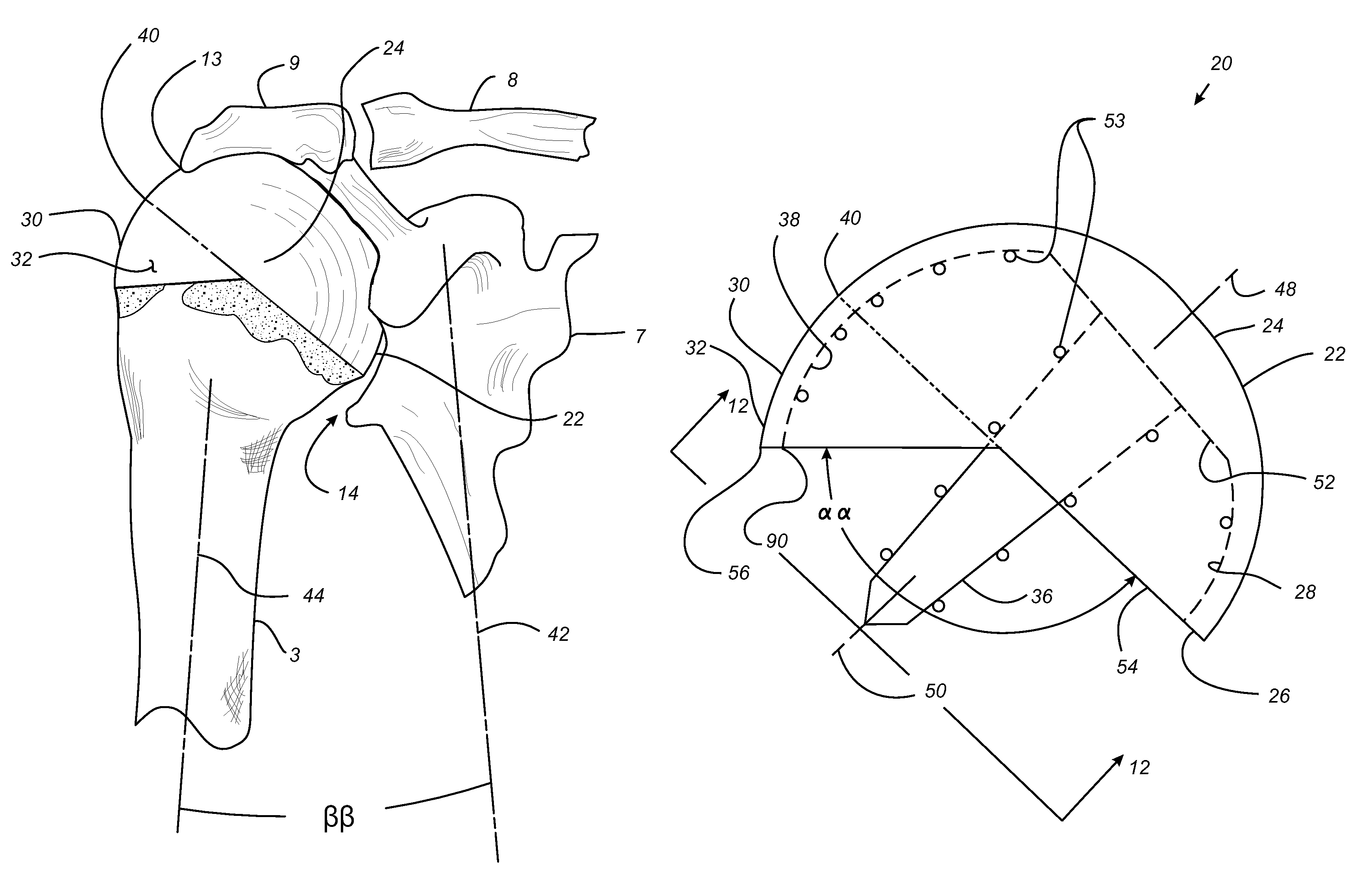
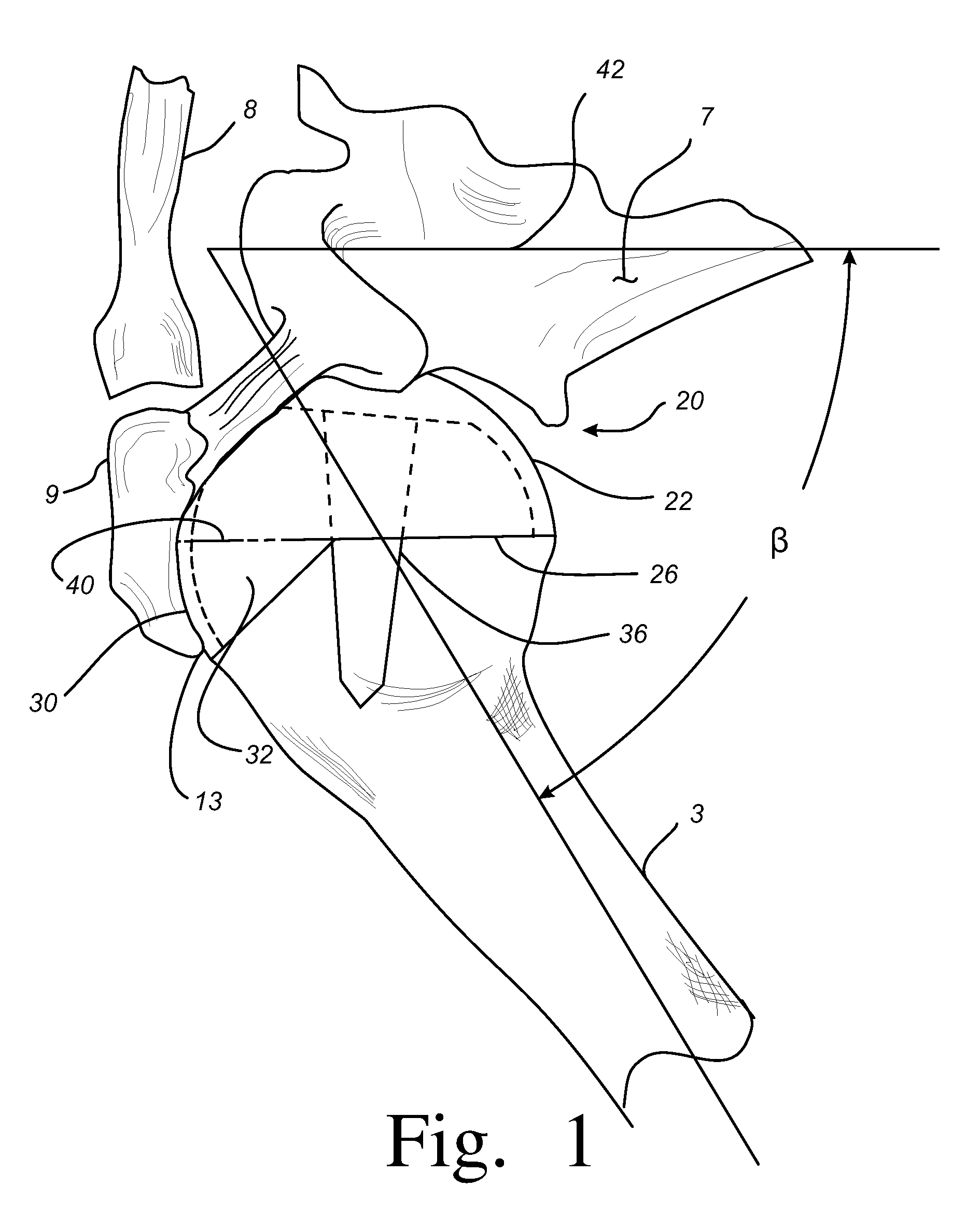
[0056]Referring now to FIG. 7, an embodiment of the present invention is shown as prosthesis 20. The prosthesis 20 is used in performing bone preserving joint arthroplasty. The prosthesis 20 is to be fitted to the head of a long bone. For example, the long bone as shown in FIG. 7 is in the form of humerus 3. The prosthesis 20 includes a first body 22 having an articulating surface 24 defining a generally circular outer periphery 26. The first body 22 also includes a second surface 28 opposed to the articulating surface 24. The second surface 28 is adapted to receive the head of the humerus 3.

[0057]The prosthesis 20 further includes a second body 30 operably associated with the first body 22. The second body 30 has a second body articulating surface 32 extendin...


PUM


Abstract

A prosthesis (20) for use in performing joint arthroplasty is provided. The prosthesis (20) is to be fitted to a long bone (3). The prosthesis includes a first body (22) having a first body articulating surface (24) defining a generally circular outer periphery (26) of the first body articulating surface (24). The first body (22) has a support surface (28) opposed to the articulating surface (24). The support surface (28) is adapted to receive the head of the long bone (3). The prosthesis (20) also includes a second body (30) operably associated with the first body (22). The second body (30) has a second body articulating surface (32) extending from a portion of the circular outer periphery (26) of the first body articulating surface (24).

Description

CROSS-REFERENCE TO RELATED APPLICATIONS[0001]Cross reference is made to the following applications: Ser. No. 10 / 403,707 entitled “ARTHROPLASTY SIZING GAGE”, Ser. No. 10 / 403,750 entitled “ARTICULATING SURFACE REPLACEMENT PROSTHESIS”, Ser. No. 10 / 403,577 entitled “MODULAR ARTICULATING SURFACE REPLACEMENT PROSTHESIS”, Ser. No. 10 / 403,710 entitled “ARTHROPLASTY INSTRUMENT AND ASSOCIATED METHOD”, and Ser. No. 10 / 403,364 entitled “PROSTHETIC IMPLANT, TRIAL AND ASSOCIATED METHOD” filed concurrently herewith which are incorporated herein by reference.TECHNICAL FIELD OF THE INVENTION[0002]The present invention relates generally to the field of orthopaedics, and more particularly, to an implant for use in arthroplasty.BACKGROUND OF THE INVENTION[0003]The invention relates to implantable articles and methods for implanting such articles. More particularly, the invention relates to a bone prosthesis and a method for implanting the same.[0004]There are known to exist many designs for and methods...

Claims


Application Information

Patent Timeline
IPC IPC(8): A61F2/40A61B17/16A61B17/17A61B17/88A61F2/00A61F2/30A61F2/36A61F2/46
CPCA61B17/15A61B17/1684A61F2/4003A61F2/4059A61B17/14A61F2/4612A61B2017/1602A61F2002/30299A61F2002/3065A61F2002/30769A61F2002/4007A61F2230/0093A61F2310/00011A61F2310/00179A61B2017/1778A61B17/1778A61F2002/30245A61B17/1642
Inventor LONG, JACK F.COON, MICHAEL E.
Owner DEPUY SYNTHES PROD INC
Why Eureka
Try Eureka