Modular vascular prosthesis and methods of use

a vascular prosthesis and module technology, applied in the field of modules, can solve the problems of limited customization options, stents that may not be suitable for some patients, and self-expanded stents are susceptible to migration, and achieve the effect of enhancing structural rigidity and articulation

Inactive Publication Date: 2011-09-27
ABBOTT LAB VASCULAR ENTERPRISE
View PDF44 Cites 19 Cited by
  • Summary
  • Abstract
  • Description
  • Claims
  • Application Information

AI Technical Summary

Benefits of technology

[0020]In view of the foregoing, it is an object of the present invention to provide a vascular prosthesis that includes a plurality of modular segments interconnected by a plurality of inter-engageable elements forming joints, which enhance articulation between adjacent segments during delivery of the prosthesis and enhance structural rigidity of the prosthesis in the deployed configuration.

Problems solved by technology

Such stents typically have homogeneous properties along the length of the stent and provide limited options for customization responsive to the needs of a particular patient.
On the other hand, self-expanding stents are susceptible to migration.
Thus, the stent may not be suitable in some patients because the fixed length of the proximal or distal region may interfere with collateral vessels upstream or downstream of the bifurcation.
One drawback of the prosthesis described in the Fogarty et al. patent is that the prosthesis may lack structural rigidity in the expanded configuration.
In particular, the patent describes no mechanism to positively engage the modules other than the liner material.
The foregoing patent also does not teach that a modular stent may be used to improve conformance of the stent to a patient's vasculature when used in a bifurcated region, or the desirability of intermixing segments including different materials, including bioabsorbable or drug-eluting segments.

Method used


Image

  • Modular vascular prosthesis and methods of use
  • Modular vascular prosthesis and methods of use
  • Modular vascular prosthesis and methods of use

Examples


Embodiment Construction

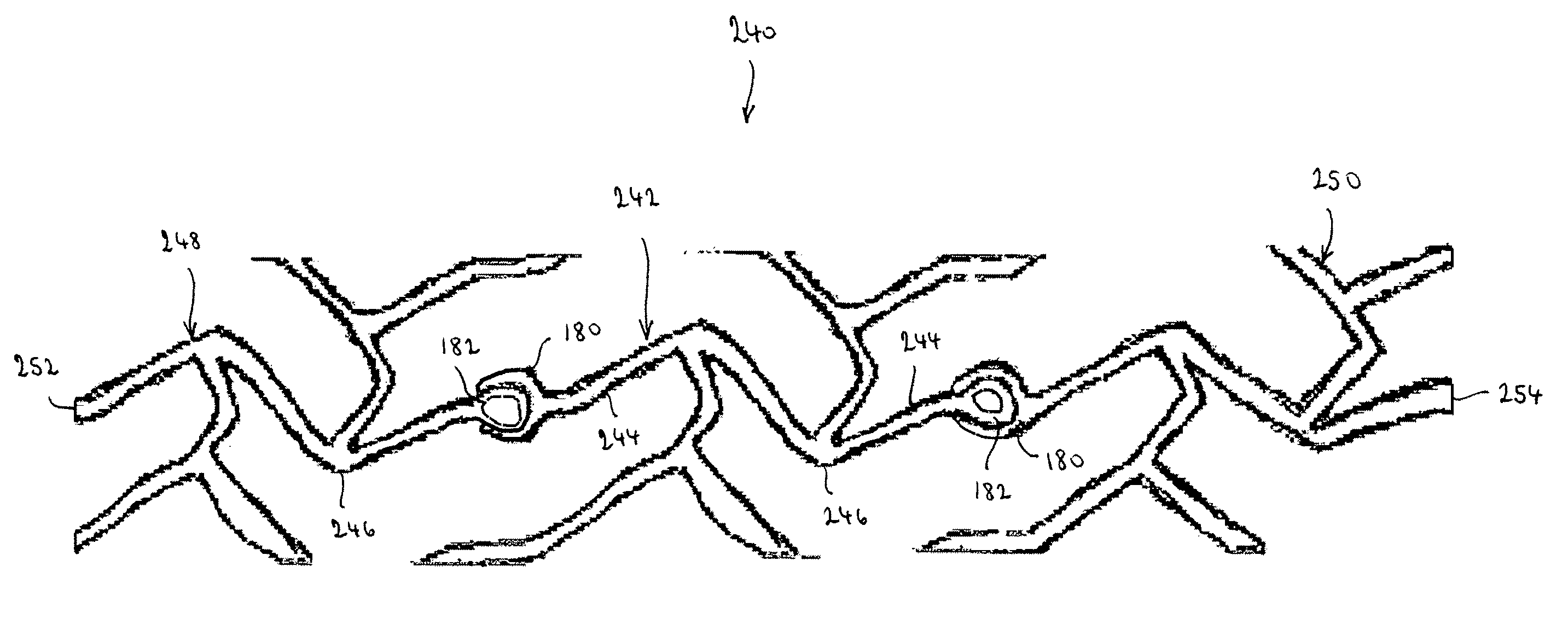
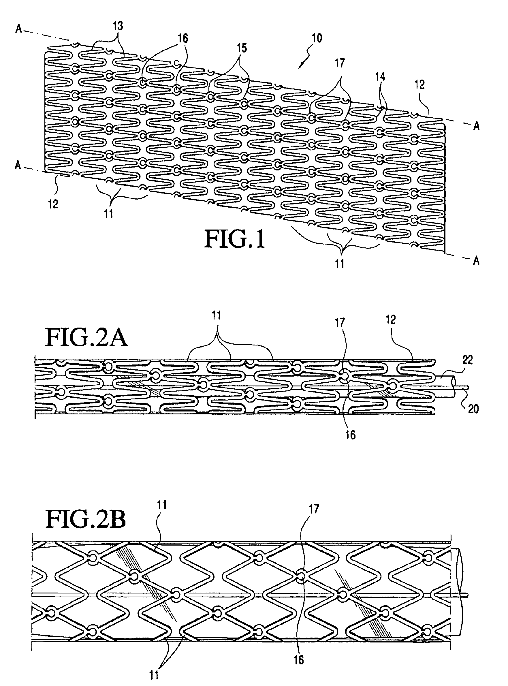
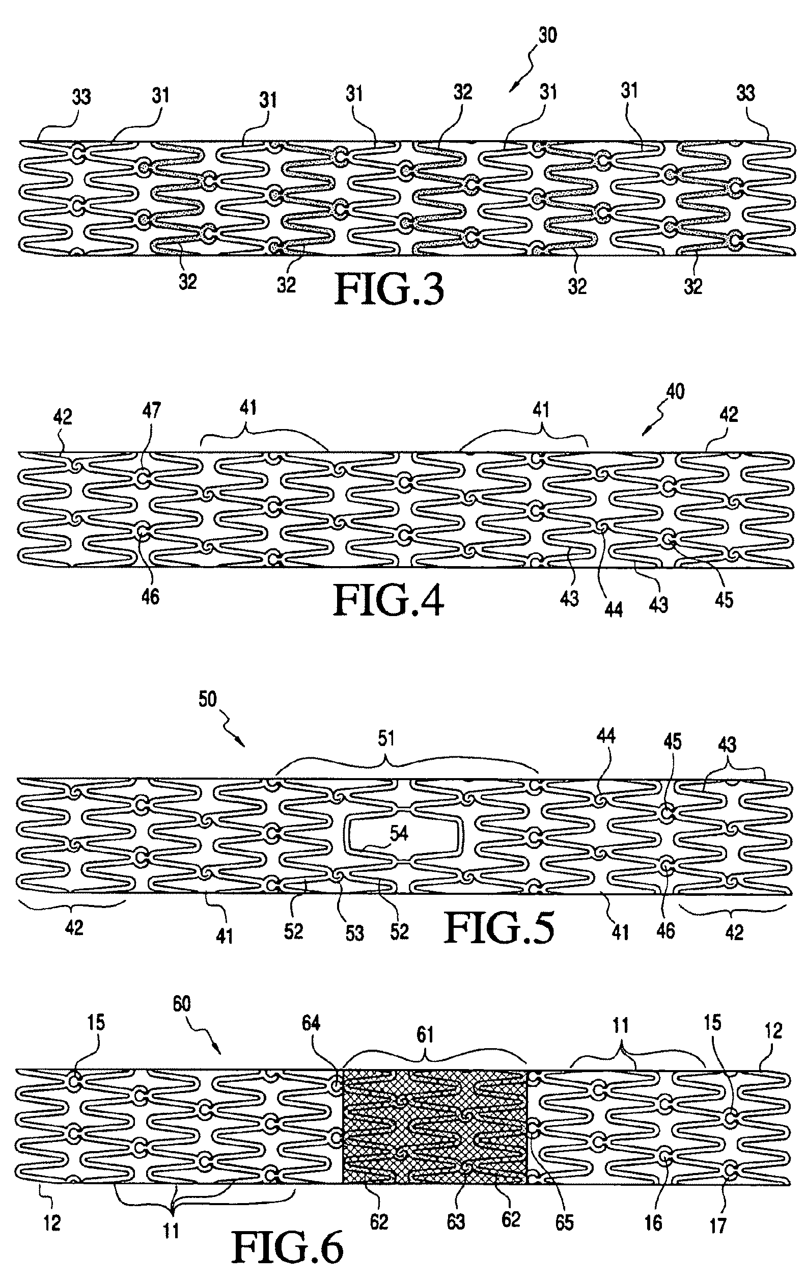
[0066]Referring to FIG. 1, a first family of embodiments of a vascular prosthesis of the present invention is described. Vascular prosthesis 10, for example, a stent, is shown cut along line A-A along its longitudinal axis and flattened into a plane for illustrative purposes. Vascular prosthesis 10 includes a tube-like structure made up of a plurality of interconnected modular segments, including inner segments 11 and end segments 12. In the illustrated embodiment, segments 11 and 12 include a plurality of struts 13 joined at the ends by bends 14 to form a generally zig-zag configuration in the deployed configuration. As would be understood by one of ordinary skill in the art, segments 11 and 12 may include many alternative strut configurations without departing from the scope of the present invention.

[0067]In accordance with the principles of the present invention, joints 15 interconnect segments 11 and 12. In a first preferred embodiment, each joint 15 includes ball element 16 eng...


PUM

PropertyMeasurementUnit
lengthsaaaaaaaaaa
lengthsaaaaaaaaaa
mechanical propertiesaaaaaaaaaa

Abstract

The present invention relates a vascular prosthesis and related assembly methods that includes a plurality of modular segments inter-engaged by flexible, and preferably lockable, inter-engageable elements forming joints or other connector areas. The segments may have a number of different mechanical properties and may be assembled by the clinician, through mechanical or chemical joining, to customize the prosthesis for a specific patient or application.

Description

CROSS-REFERENCE TO RELATED APPLICATIONS[0001]The present application is a continuation-in-part of U.S. patent application Ser. No. 11 / 067,090, filed on Feb. 25, 2005 and published on Aug. 31, 2006 as U.S. Patent Application Publication No. 2006 / 0195175.FIELD OF THE INVENTION[0002]The present invention relates to modular vascular prostheses, such as stents, and related methods of use. More particularly, the present invention relates to vascular prostheses having a modular construction that permits the properties and length of the prosthesis to be customized for a specific patient.BACKGROUND OF THE INVENTION[0003]Numerous stent designs are known in the art, of which self-expanding and balloon-expandable stents are the predominant commercially available types. Self-expanding stents, such as the stents described in U.S. Pat. No. 4,580,568 to Gianturco, generally provide good crush-resistance and axially flexibility, thus permitting delivery through tortuous anatomy, but provide lower ra...

Claims


Application Information

Patent Timeline
Patent Type & Authority Patents(United States)
IPC IPC(8): A61F2/86
CPCA61F2/91A61F2/89A61F2/915A61F2002/91558A61F2002/91525A61F2002/91566A61F2220/0025A61F2002/30428A61F2002/91541A61F2002/30677A61F2250/0048A61F2002/91591Y10T29/49826A61F2250/0063A61F2/852A61F2002/30611A61F2220/0058A61F2002/30019A61F2250/0067A61F2220/0033A61F2002/30604
Inventor STRAUSS, DAVID P.BIALAS, MICHAEL R.DEMORE, DUANEBARBIER, ROBERTBREGULLA, RAINER
Owner ABBOTT LAB VASCULAR ENTERPRISE
Why Eureka
Try Eureka