
Methods and apparatus for surgical retraction

a tissue retractor and surgical technology, applied in the field of surgical retractor systems, can solve the problems of obstructing the surgical team's access to the patient, time-consuming and complex setup, and requiring frame assemblies to mount the tabl

Inactive Publication Date: 2009-03-05
SPINEOLOGY
View PDF5 Cites 19 Cited by
  • Summary
  • Abstract
  • Description
  • Claims
  • Application Information

AI Technical Summary

Benefits of technology

[0009]According to one aspect of the present invention, articulation of the blades at the surgical site creates a locking hold in the incision area such that the device is self-supporting.
[0013]In an embodiment of the present invention, each side of the retractor may be adjusted independently of the other. According to one aspect, the blades may retract and articulate simultaneously. In one embodiment, the articulation and retraction occur in a direct relationship, such that the more retraction occurs the more articulation will occur. In this embodiment, increased articulation with increasing retraction enhances the self-locking stability of the device as surgical exposure is increased.
[0016]According to one aspect of the present invention, the retractor may form a base or platform to maintain the position of an access portal that can be used to deliver or remove tissue, bone, implants or other items necessary for a particular surgical procedure. The position of the access portal may be maintained while simultaneously maintaining visualization of the anatomy and maintaining the access trajectory.

Problems solved by technology

Unfortunately, table mounting requires a frame assembly that can be time consuming and complex to set up.
Further, generally the table mounting assemblies are generally large and can obstruct the surgical team's access to the patient.
Because the entire assembly is engaged to the bone, the device required a relatively large access opening and is limited in its use to those procedures adjacent to a bone structure that is large enough and sturdy enough to support the retractor frame.

Method used


Image

  • Methods and apparatus for surgical retraction
  • Methods and apparatus for surgical retraction
  • Methods and apparatus for surgical retraction

Examples


Embodiment Construction

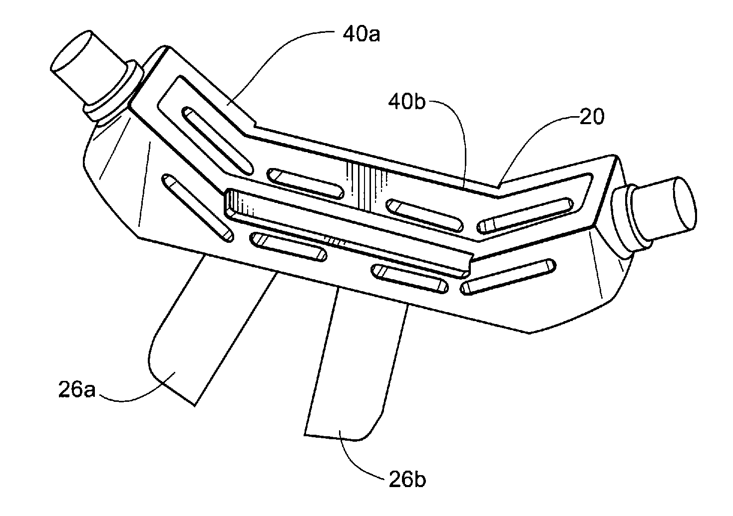
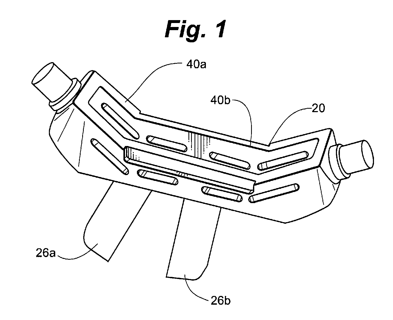
[0023]Referring to FIG. 1, there can be seen a retractor according to one embodiment of the present disclosure. In the embodiment shown in FIG. 1, retractor 10 includes a frame 20 and a removable blade set having blades 26a and 26b. It is noted that the retractor may include more than two blades. For example, it may be desirable to retract in a transverse plane. In such a case the retractor may include more than two blades and correspondingly more than two blade holders.

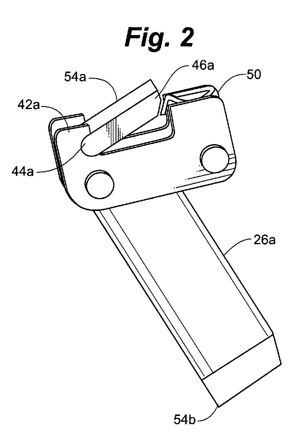
[0024]In one embodiment, blades 26a and 26b may be selected from a variety of blade lengths ranging from about 25 mm to about 100 mm. The blade length may be selected such that the blades reach the desired depth required by a particular patient's anatomy and the particular surgical procedure being performed. According to one aspect, blades 26a and 26b may include driving edges that may be tapered to fit closely over a dilator. In an embodiment, the driving edges may enable the blades 26a and 26b to twist down into po...


PUM


Abstract

The present invention provides method and apparatus that may be patient mounted for surgical retraction. The retractor disclosed herein may be positioned with a base plate resting against the patient's skin surface. In one embodiment, retractor blades extending into the patient's body from the base plate of the retractor device may be adapted to be inserted in a closed position for minimally invasive access, and adapted to be moved away from each other in a controlled fashion to create the desired surgical retraction of soft tissue. Because the blades are inserted in a closed position, the skin incision is small compared to the available exposure of nerves and delicate tissue.

Description

RELATED APPLICATION[0001]This application claims the benefit of U.S. Provisional Application No. 60 / 920,000, filed Mar. 26, 2007, which is hereby fully incorporated herein by reference.FIELD OF THE INVENTION[0002]The present invention relates generally to a method and apparatus for retracting tissue in a surgical procedure. More particularly, the present invention relates to a surgical retractor system adapted to be patient mounted and / or utilizes two or more blades to create and maintain a minimally invasive patient access.BACKGROUND OF THE INVENTION[0003]Surgical retractors are commonly used to move a patient's tissue apart in order to provide a surgeon with an operating field. There exist a myriad of surgical retractors. Most are manual instruments held in place by the surgeon or a surgical assistant. There also are retractors that are mounted on the operating table via some form of a frame system and a post device that mounts to the rails on the operating table. Table-mounted sy...

Claims


Application Information

Patent Timeline
Patent Type & Authority Applications(United States)
IPC IPC(8): A61B1/32
CPCA61B17/0206A61B2019/306A61B2017/0256A61B17/025A61B2090/036
Inventor BJORK, TODD M.MCPHILLIPS, DAN
Owner SPINEOLOGY
Learn More