
Humidification system

Active Publication Date: 2012-05-24
VYAIRE MEDICAL CONSUMABLES LLC
View PDF15 Cites 56 Cited by
  • Summary
  • Abstract
  • Description
  • Claims
  • Application Information

AI Technical Summary

Benefits of technology

[0009]The present invention provides a method of reducing condensed humidifying agent in a humidification system, the method includes providing a humidification system having a respiratory circuit for delivering a volume of gas to a patient and a humidifier portion for delivering a humidifying agent to the volume of gas, pulsing a delivery of the humidifying agent to the volume of gas at a pulsed interval via the humidifier portion, heating the volume of gas, and vaporizing, during a non-pulsed interval, condensed humidifying agent present in the respiratory circuit to reduce the condensed humidifying agent present in the humidification system.

Problems solved by technology

However, heating the body of water to a point sufficient to produce water vapor can take a significant amount of time, depending on the amount of water contained in the chamber.
However, operating the system in this manner requires implementing sensors for determining relative and absolute humidity of the gas.
Furthermore, it would not be comfortable for the patient to have bulky equipment located directly by the patient's face.
However, using a respiratory circuit to deliver the humidified gas creates additional problems.
A significant problem that occurs when using a respiratory circuit to deliver humidified gas is the formation of condensation in the respiratory circuit.
After too much condensation builds up, a practitioner must manually remove the condensation from the respiratory circuit because it is dangerous for a patient to accidentally inhale liquid.
The manual removal of condensation requires taking apart the respiratory circuit or replacing the respiratory circuit, which can take a substantial amount of time.
Furthermore opening the circuit to remove condensation causes a loss of respiratory pressure support and may result in alelactasis or respiratory distress.
However, these systems require additional heated elements and controls to heat the respiratory circuit walls and the gas to reduce the condensation.

Method used


Image

  • Humidification system
  • Humidification system
  • Humidification system

Examples


Embodiment Construction

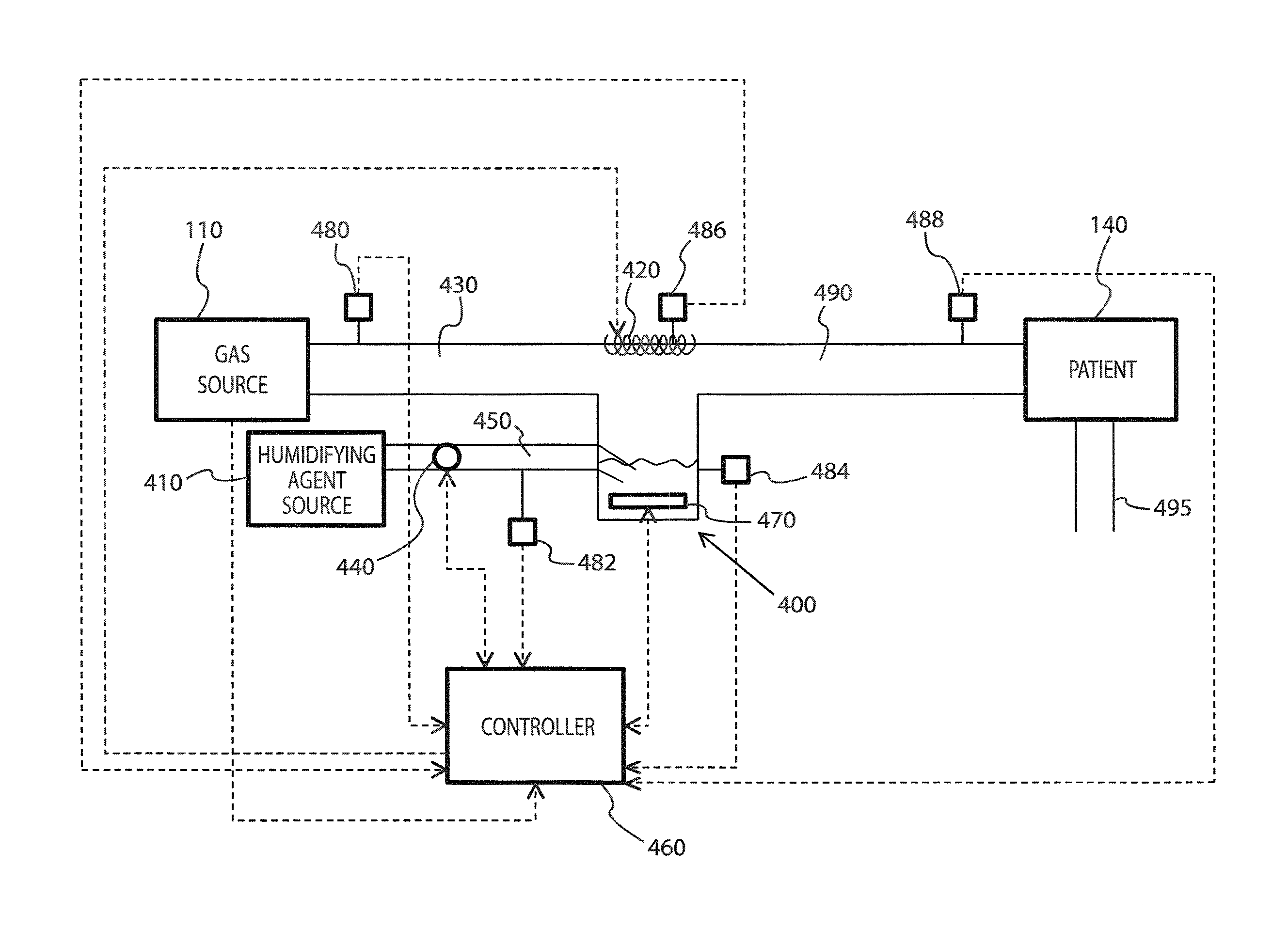
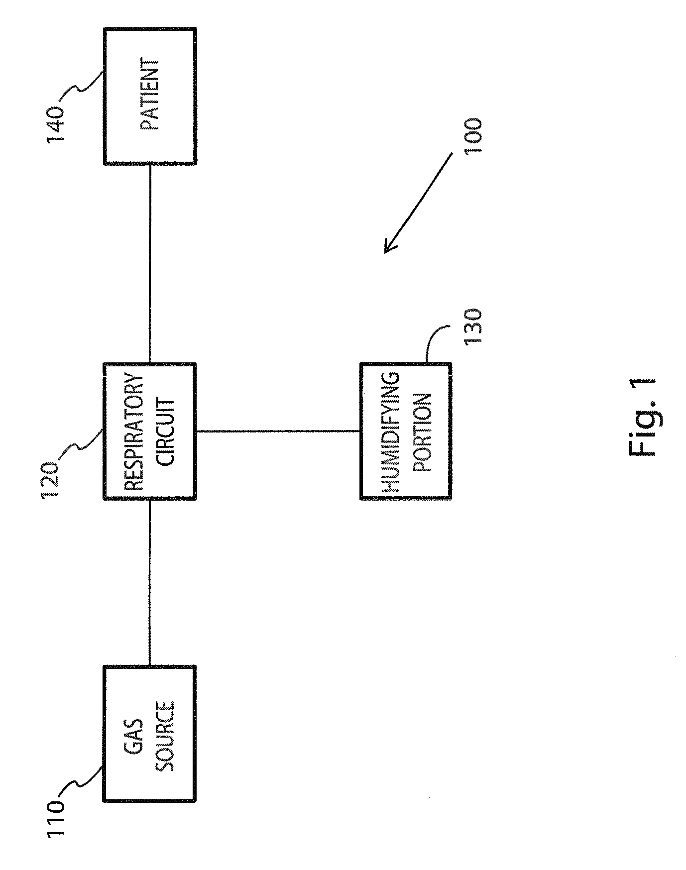
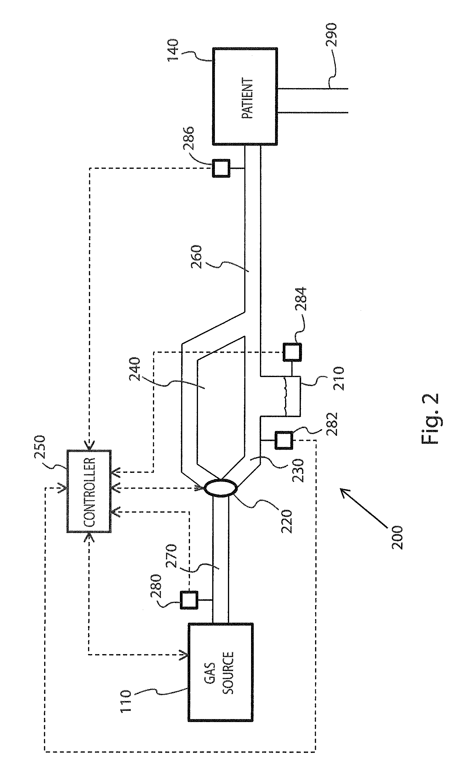
[0017]The present invention provides a method of removing condensed humidifying agent from a humidification system, a method of delivering humidifying gas to a patient, and a humidification system for performing the methods. It is to be understood that the term gas is intended to include any gas suitable for use with the following disclosure. For example, the gas may comprise oxygen, ambient air, or any other breathable gas. The method of removing condensed humidifying agent includes pulsing the delivery of a humidifying agent to a heated volume of gas as the volume of gas travels towards the patient and evaporating the condensed humidifying agent during a non-pulsed interval. The method of delivering humidified gas to the patient includes delivering a controlled amount of humidifying agent to a humidifier portion. Thus, the present invention effectively and easily allows a practitioner to reduce condensation present in a humidification system by removing condensation. Furthermore, ...


PUM


Abstract

The present invention provides a method and apparatus for reducing condensed humidifying agent in a humidification system by pulsing a delivery of humidifying agent into a respiratory circuit. During a non-pulsed interval, gas flowing through the respiratory circuit will evaporate the condensed humidifying agent present in the respiratory circuit. The present invention also provides a method and apparatus for delivering humidified gas to a patient, wherein the delivery avoids the problems associated with a stationary water humidifier. In the method, the delivery of humidifying agent is precisely controlled to deliver a flow of humidifying agent to a volume of gas.

Description

FIELD OF THE INVENTION[0001]Aspects of the present invention relate to humidification systems which provide humidified gas to a patient.BACKGROUND OF THE INVENTION[0002]Humidification systems have long been used to treat patients in need of respiratory assistance. A typical humidification system generally includes a source of gas, a source of water vapor, and a delivery system. In the typical humidification systems, the water vapor is first produced by heating a stationary body of water contained in a humidifying chamber. Then, the water vapor mixes with gases passing through the humidifying chamber, thereby humidifying the gas. However, heating the body of water to a point sufficient to produce water vapor can take a significant amount of time, depending on the amount of water contained in the chamber. In the stationary water humidifier, the humidifying chamber containing the water is arranged so that the water vapor mixes with the gas flowing through the humidifying chamber, there...

Claims


Application Information

Patent Timeline
IPC IPC(8): A61M16/16
CPCA61M11/005A61M16/16A61M16/162A61M16/20A61M16/161A61M2205/3368A61M16/1085A61M16/109A61M2016/0039A61M11/042A61M16/024A61M16/0003
Inventor KORNEFF, NEIL ALEXDIXON, PAUL DAVIDVARGA, CHRISTOPHER M.
Owner VYAIRE MEDICAL CONSUMABLES LLC
Learn More